
Collab 2020: Modeling Heavy Equipment (Backhoe)
Forum Archive › Collab 2020: Modeling Heavy Equipment (Backhoe)
- This topic has 1,439 replies, 27 voices, and was last updated 4 years, 1 month ago by
Omar Domenech.
-
AuthorPosts
-
May 11, 2020 at 1:36 pm #54212
I’m not picky @spikeyxxx anything is better than how I was doing it. Haha
May 11, 2020 at 2:29 pm #54213@blanchsb and @theluthier I remember now how I did this, actually used Empties and Bones, sort of like this (the set-up is symmetrical):
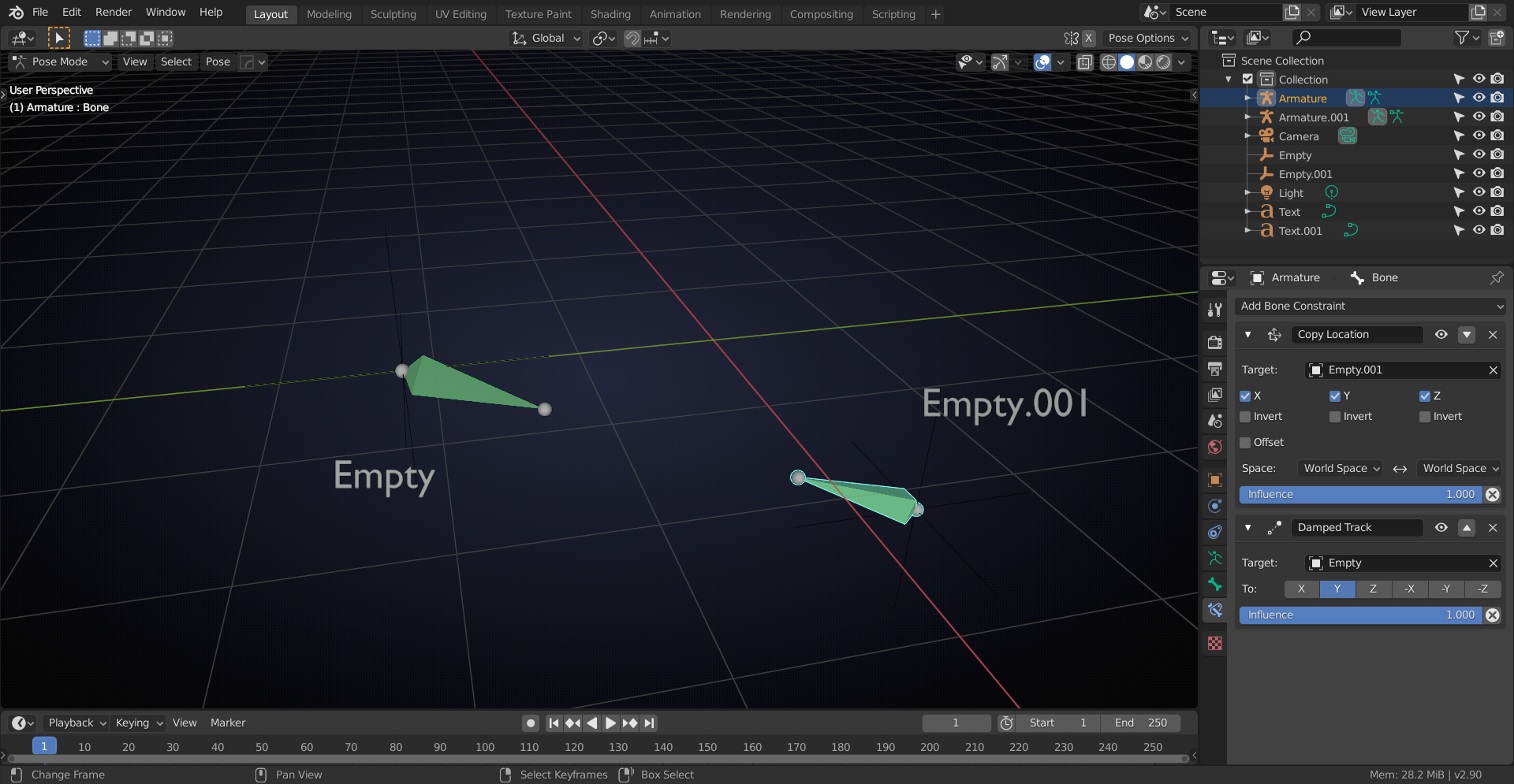
I’m not a rigger and @waylow will probably laugh at how ‘clumsy’ this is, but, in trying to avoid circular dependencies, I ended up with this;)
May 11, 2020 at 2:51 pm #54214Interesting…….kinda hard for my brain to follow just looking at it since I have never done this but I will try to replicate it on something simple and reply if I have questions. Thanks @spikeyxxx
I feel bad for Wayne trying to play catchup (but feel free to play with kechup/ketchup/catsup) on this forum posting haha.
P.S. I am a Heinz Ketchup guy myself.
May 11, 2020 at 2:56 pm #54215@blanchsb each Bone is at the position of one Empty (Copy Location Constraint) and pointing at the other Empty (Damped Track Constraint).
May 11, 2020 at 3:05 pm #54216@jakeblended same here I just added materials so you can see.
I’ve been tearing apart my cab again lol smh I keep seeing new things.
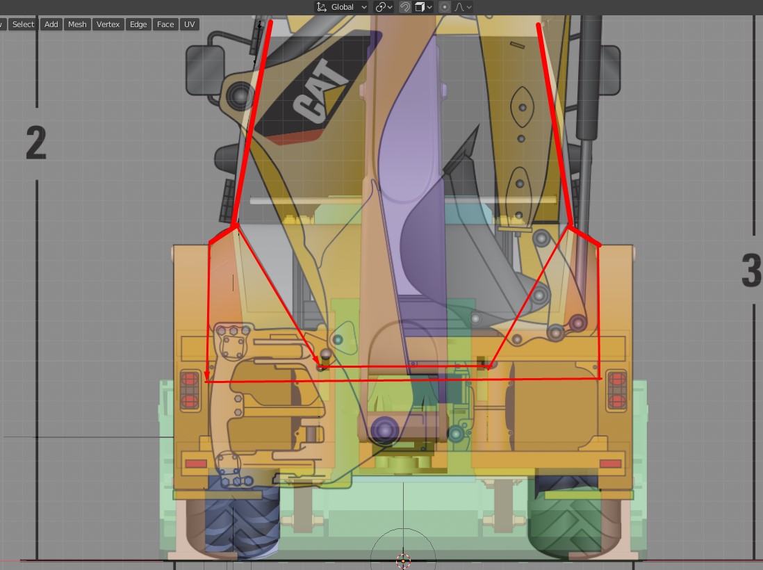
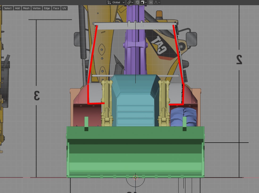
@adrian2301 at the front, back and side views I keep seeing that the back lower part of the cab gets narrower than the front. So I’m going to stop where I’m at because I keep trying to match the wheel cover thingy…yea I’m a girl and I know nothing about the mechanics of things…I really don’t know what I was thinking lol
Here is the Back view.
 And here is the front view
 May 11, 2020 at 3:13 pm #54217
Forgive me @blanchsb and @spikeyxxx…but I’m having a hard time understanding the difficulty at hand 😅 Clearly you two get it though, so it’s just me not understanding.
With constraints involved, it almost sounds like you two are talking about how the model correlates to the final kinetic functionality of the mechanism (?)
Perhaps I’m not clear about what needs aligning to what. Based on the screenshot I’m seeing circles being connected by straight lines which is..well..straight forward.
If you could record a video of your screen and your voice describing the issue, that’s probably the best way for me to understand.
I’m sorry! I feel so dumb 😫
May 11, 2020 at 3:24 pm #54218@theluthier don’t feel dumb!
Basically you have a hydraulic cylinder like this:
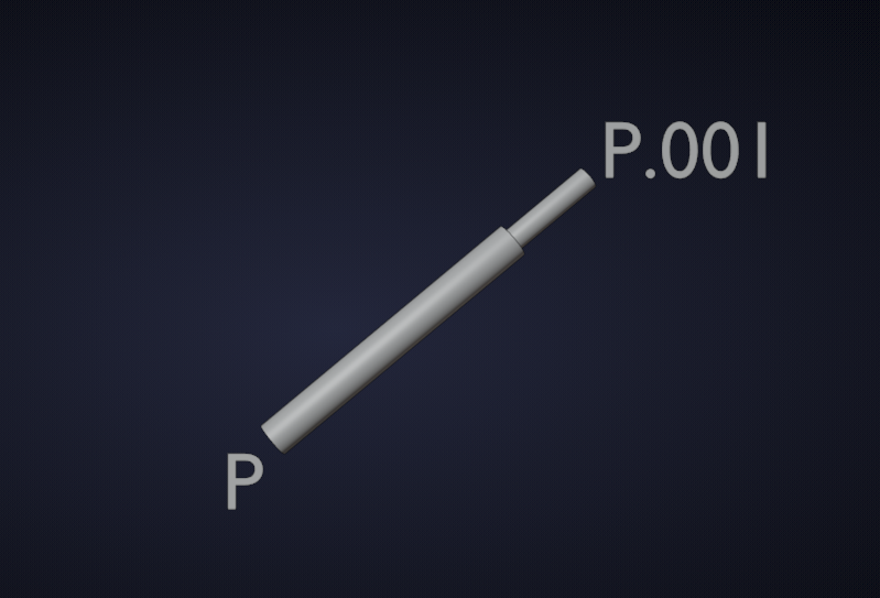
and you need to snap point P to a certain position as well as point P.001.
Try this without looking at my solution…
May 11, 2020 at 4:35 pm #54219@spikeyxxx not only explained it well with one sentence but provided a clear picture! What a stud.
@theluthier Let say that P and P.001 were not aligned in the first place and now your job it to align them. P must point at P.001 and yet P.001 must also Point at P. How to do that without a circular argument makes my head hurt haha.
If I need to move P around to re-position it Then I want P and P.001 to keep looking at each other.
This is what knowing this will solve for me:
Basically I have to line my assembly up with:
1 Align with Itself (I have lots of objects that pivot and join together on both ends within my loader arm assembly) AND
2 Align with the Loader Bucket on one end AND
3 Align with the Chassis on the other end.
If I modeled everything together I could completely control all of that but at this point I am depending on @pfbourassa‘s changes and the changes from @adrian2301 for the chassis. Currently I have #1 and #2 under control but I am having a hard time getting my entire assembly moving to align to #3 while maintaining that relationship to #1 and #2. It’s been turning into a little of a nightmare haha. If @pfbourassa or @adrian2301 moves their pin holes because they needs more room then I need to be able to adjust my assembly accordingly to match them. My part is the middle man and should probably conform to the others
@spikeyxxx is on point with perhaps bones/empties/contraints. I am not so much concerned about the animation as I am about keeping things lined up if there are any more changes.
May 11, 2020 at 4:38 pm #54220@jakeblended I was afraid other priorities had trumped your swing frame progress this assignment period! I’m glad that wasn’t the case. You’d done an awesome job on your new and improved swing frame 👏
I think [Kent] could perhaps give some good tips on how to charm one of these snakes in the stream.
@blanchsb I initially planned to cover hydraulic lines but other things have pushed it down the list. If time runs out tomorrow, definitely next stream 👍
May 11, 2020 at 4:40 pm #54221@blanchsb indeed, this is not about animation, but using a rig to model things correctly…Thinking outside the box here.
May 11, 2020 at 4:43 pm #54222AHHH OK you both have cleared it up for me! Thanks for the patience, guys.
I think Spikey’s damped track constraint is the best method. I’ll certainly go over this tomorrow 👍
May 11, 2020 at 5:59 pm #54223So……. I know a little about mechanics and engineering, I’m no expert but here goes:
The idea of the hydraulic piston is for Part A to be pushed and pulled in and out of Part B, In this example P.001 would be aligned with the chassis, but the rotation is free, meaning there is no force rotating P.001. The rotation of P.001 happens when the arm is lifted or lowered by a separate piston. If P is attached to the bucket, the push and pull of this piston is to rotate the bucket, so with the piston extended, or pushed, the teeth of the bucket would point towards the ground, and when retracted, or pulled, then the teeth would point towards the sky.
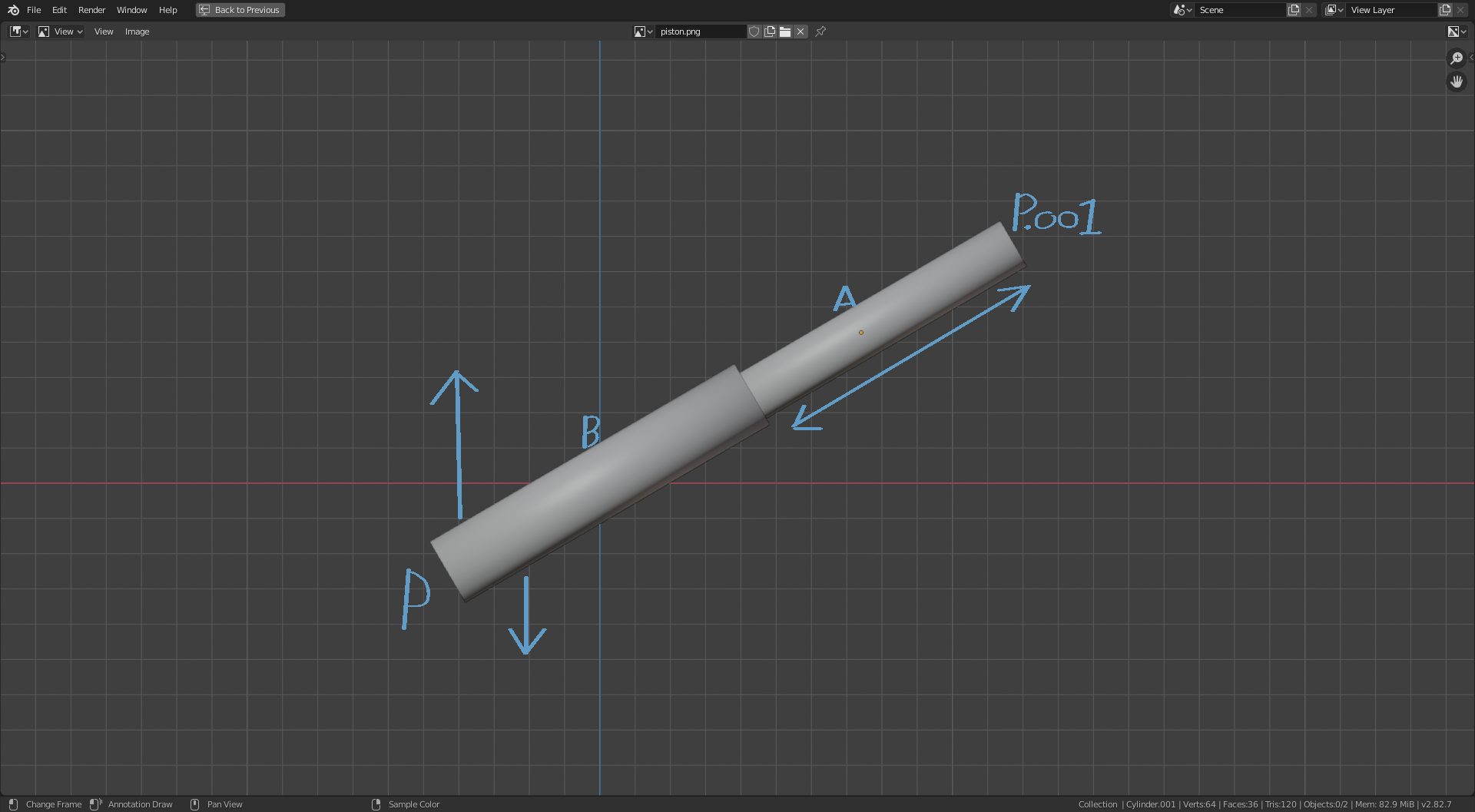
So this would suggest that P.001 would be constrained in location only, or aligned with the chassis, but free to rotate. The other point to consider is that parts A and B must always be aligned exactly on the same axis. The rotation of the bucket at P is dependent on the position of A in relation to B along this axis. So this piston controls rotation at P or more precisely the rotation of the bucket. The rotation at P.001 is controlled by the movement of other parts, or the lifting of the arm by another piston, But the location of P.001 in relation to the chassis will always stay the same. Part B would move along or over Part A.
So to do this in Blender:
I WOULDN’T HAVE A CLUE
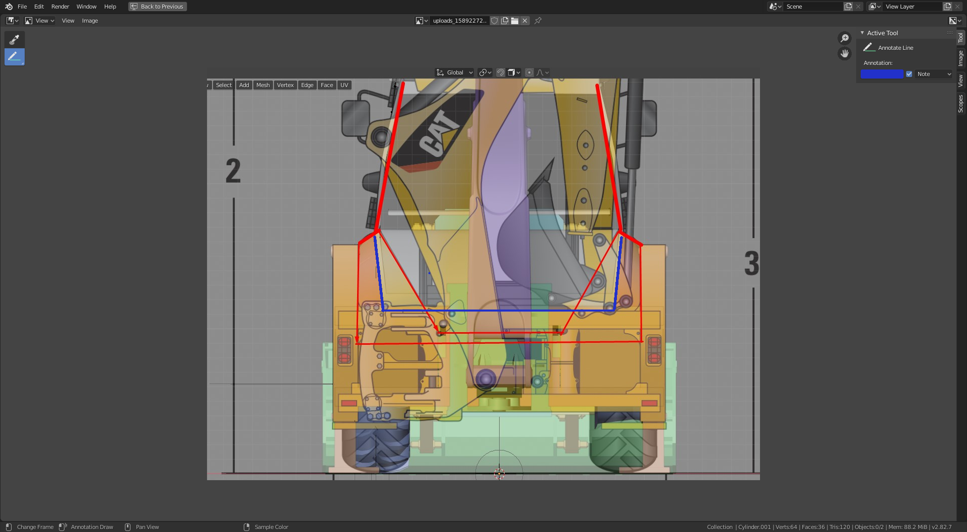
May 11, 2020 at 6:19 pm #54224OK @ketre , The Fenders as they say in some parts, wheel arches in others, are not quite complete, as to say they need to be extended in the x direction in towards the cab so I would ignore them as a reference for now I was going to wait and use the cab as reference. But your right the cab has got an awkward shape, it probably is shaped around the fenders, but I wouldn’t worry about trying to do that. I would suggest at the point where the angle changes just above the fenders, it should be more or less vertical or even angled inwards. See the blue lines I have added to this Image. It wont go any lower than this as that is approximate height of the chassis. but I would go with this for now.
 May 11, 2020 at 7:41 pm #54225
@adrian2301 all right, here we go – I’ve got the “clamps” on the back of the slide frame, and adjusted the cylinders for the correct clearance:
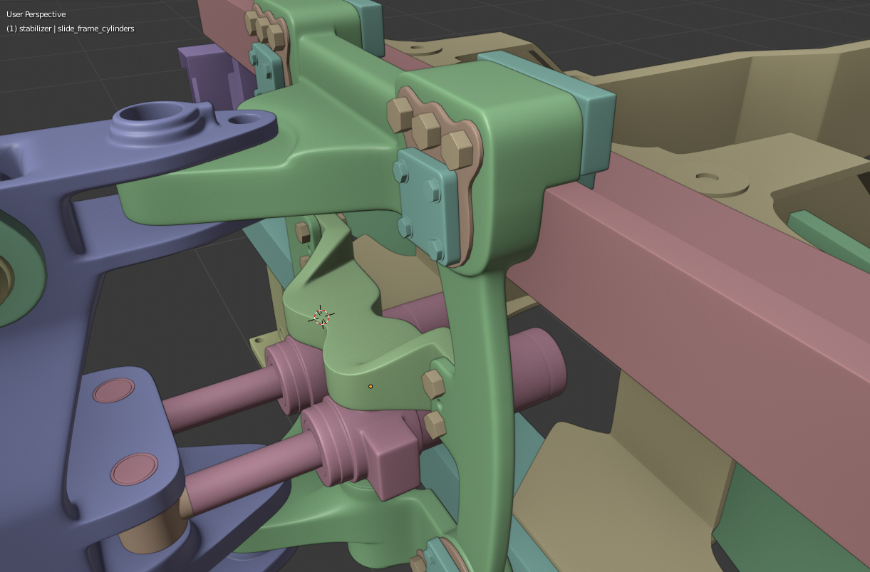
Here is my updated file – but, I already submitted my previous file to Kent on Saturday, so these corrections probably won’t make it into the stream unless Kent grabs them at the last moment, ha!
@ketre you know what I bet would REALLY help you with that – and help a bunch of other people’s components too – is a decent top-down plan view of the whole backhoe, but for the life of me I just can’t find one – not even on that website with all the part diagrams. It’s super-frustrating!
May 11, 2020 at 8:18 pm #54226I figured it out @spikeyxxx @adrian2301 @theluthier . Thanks to Spikey for the clear explanation. I mainly want this as a part of my assembly to assist me in moving my parts so that I mate up to the Chassis and Loader Bucket and also maintain my assembly’s relationships for each part to one another. This will help me roll with the design punches if anyone needs to move any pivot points. Maybe I do want Wayne’s input as well since I am 1/64th Aussie. @waylow feel free to tear my thought process apart.
Enjoy the video and give feedback (best watched at 1080p). My voice is extremely alluring and should keep you awake for maybe 30 seconds of the 2 minutes, haha.
-
AuthorPosts


- The topic ‘Collab 2020: Modeling Heavy Equipment (Backhoe)’ is closed to new replies.