
Backhoe Contribution – Blanchsb – Exterior Loader Arms and Interior Chair
Forum Archive › Backhoe Contribution – Blanchsb – Exterior Loader Arms and Interior Chair
- This topic has 215 replies, 9 voices, and was last updated 5 years, 10 months ago by
Rita Geraghty.
-
AuthorPosts
-
May 31, 2020 at 7:21 pm #56839
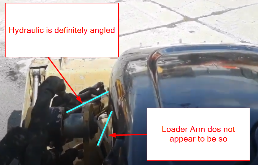
Found another video and I am convinced the hydraulics are shoved over a lot: When he gets inside the cab you can definitely tell: (at the end of the video): https://youtu.be/lK5J_Hg3vMk?t=162
 June 1, 2020 at 2:56 pm #56840
Hmmm I dunno man..I’m comparing these photos to our others, and the model. I gotta say I’m not entirely convinced the hydraulic is angled from the loader arm. Mainly because the loader arm has a curved top edge that makes a slight angle hard to determine. Also the perspective camera angle is highly suspect for judging things like this.
I suppose the reason I’m replying is to push back if you’re thinking to make major changes. Maybe they’re not that major in which case sure, give it a try and see it if works better.
My money would be on them oriented straight from above though. That’s just my 2¢
Does an angled hydraulic solve another issue you’ve run into?
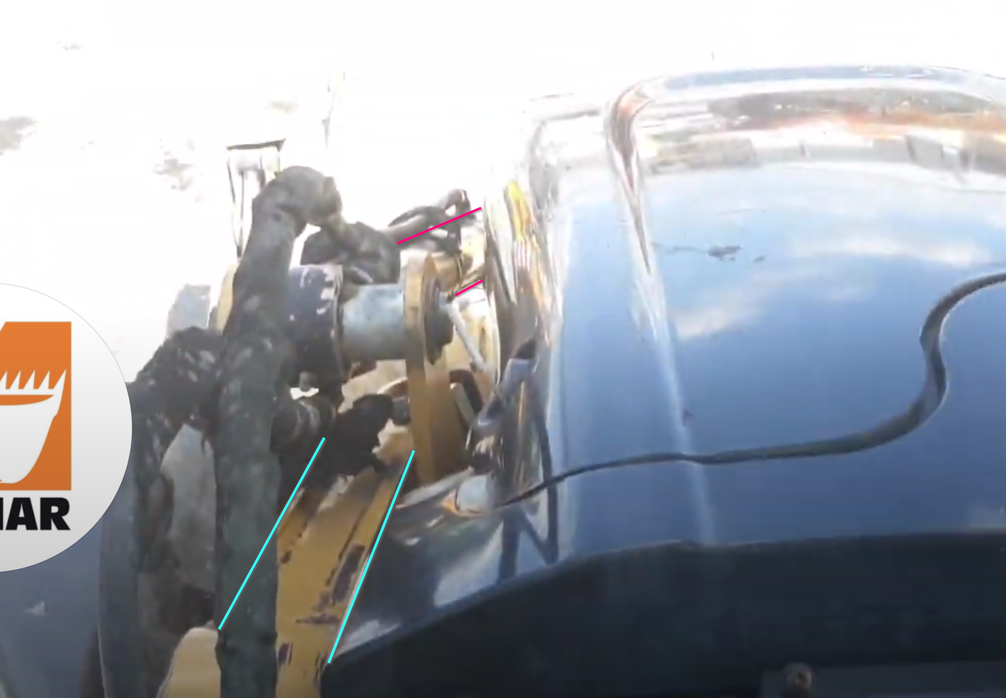
June 2, 2020 at 5:41 pm #56841@theluthier this is a better still from the video: Red lines are the hydraulic angle, and the blue is the main loader arm. Notice how the hydraulic is shoved over to one side on it’s rotating pin?
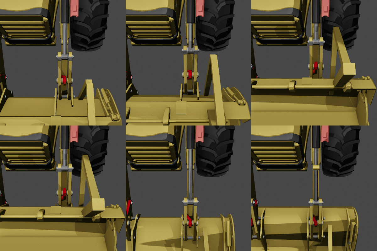
The main problem is that red shape from earlier: I originally modeled it as an angled bracket but it is indeed straight after referencing a lot of schematics.
In order for that red piece (in the gif below) to not interfere it must move left along with it’s top connector plates. So there are 2 things that could make this happen
1. The loader arms needs to bend to the right (in the gif below)
or
2. the hydraulic needs to point to left (in the gif below).From a mechanical build standpoint it makes more sense for the hydraulic to point left. Plate metal is not easy to bend, not that it isn’t possible but it would be easier to point the hydraulic. I need to make some of those plates a little thinner too. They are a little too fat.
Adrian pointed this out that the top connects to a different part of the main bucket than the bottom:
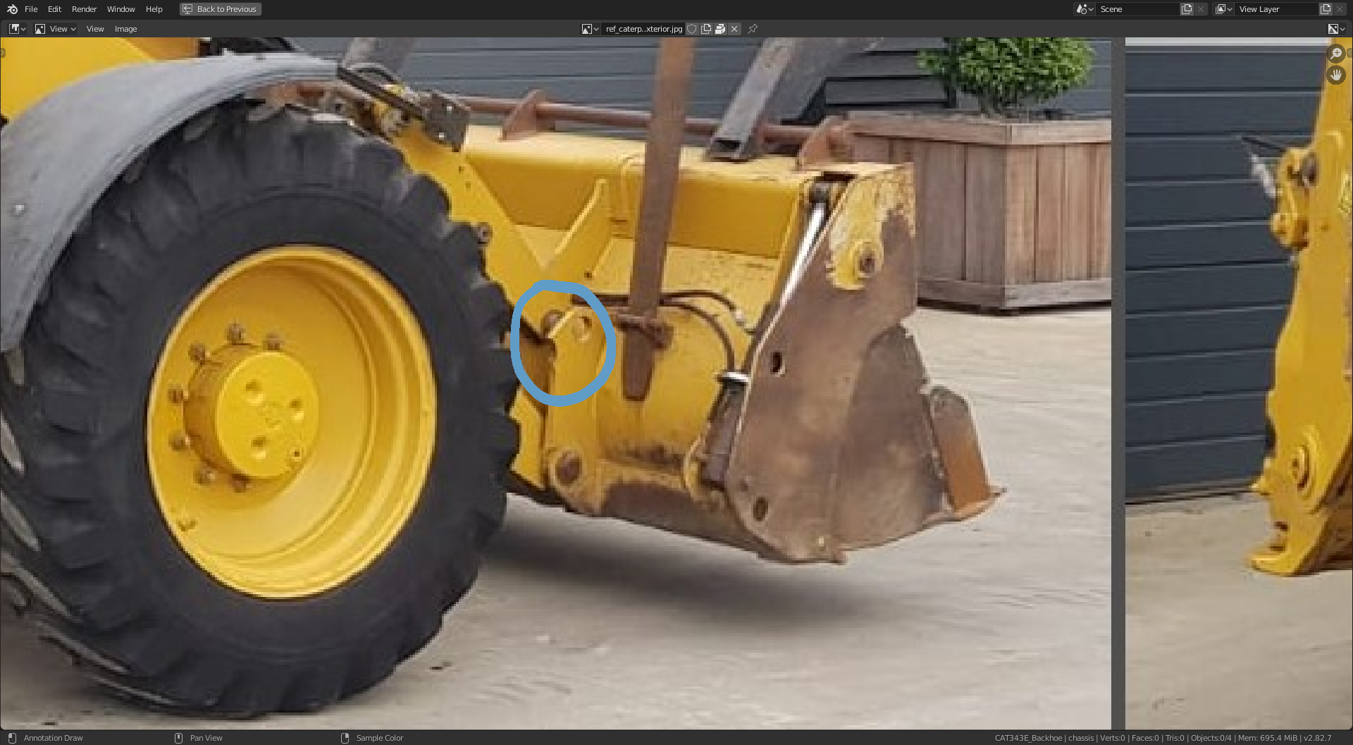 So those top plate pieces attaching to the NON-Angled Bracket (red piece in the gif) are definitely inside from where the loader arm attaches.
Hopefully I am explaining it.
June 2, 2020 at 5:53 pm #56842Here’s another cool reference video that shows the good angle: It’s doing a snow plow. Notice how the hydraulic is shoved over where it pins (at the bottom of the image ) to make the angle too
https://www.youtube.com/watch?v=hmaLFZJ40JU
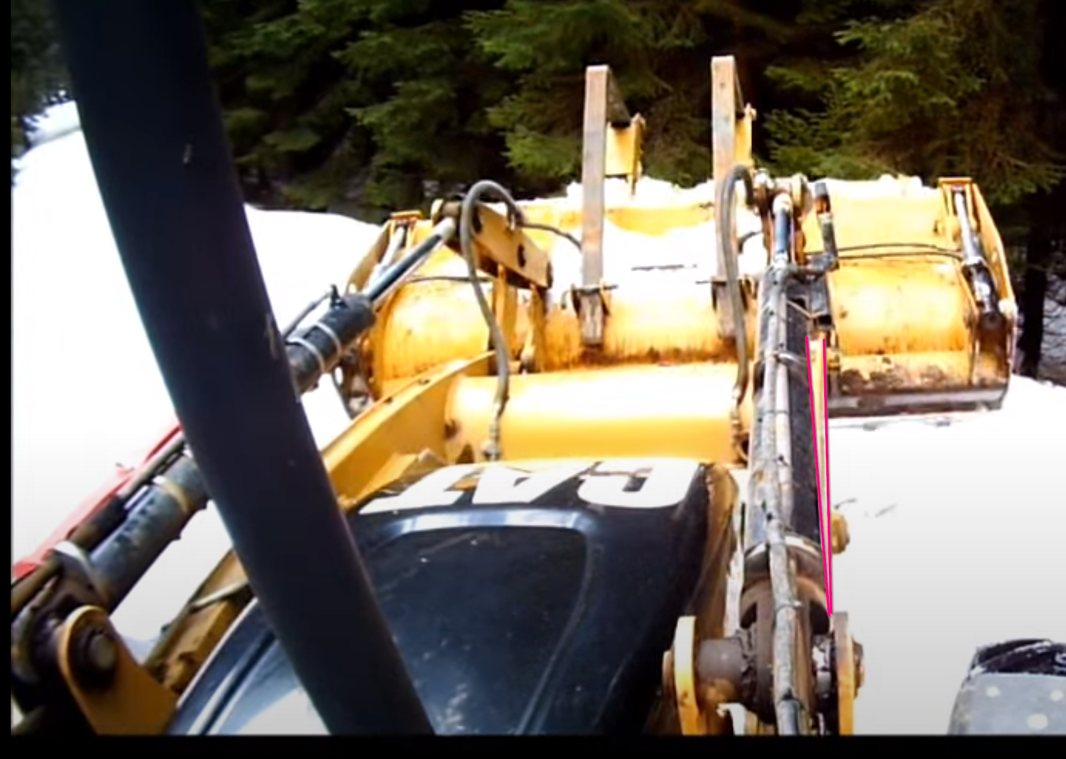
It’s not a huge angle but I believe it points towards the inside from this reference
June 2, 2020 at 10:09 pm #56843Shawn, I think that you had a comment in the main thread about a potential conflict between your loader arm and my engine housing. I think there is, and I am sorry it took me so long to respond. However, I’m also not sure if Kent is using my engine housing or Artifacts.
So perhaps you might want to check with Artifact to see if they have a potential conflict problem or not. I have uploaded my recent version into dropbox so you can view it here:
https://www.dropbox.com/s/88gojjldut9lk2w/Engine_block_04c_coord.blend?dl=0
The hood rotates about it’s origin there in the front, so just rotate it about the x axis about 5 degrees and you can see the conflict.
Sorry it took me so long to reply hope I’m not too late to help you out.
June 3, 2020 at 11:53 am #56844Thanks @doulos4iesou i will take a look after work.
June 5, 2020 at 1:03 pm #56845I promise I don’t mean to be argumentative, but I still think it’s the curve of the loader arm causing visual confusion. With perspective involved it could even look like the left loader arm is angled inward:
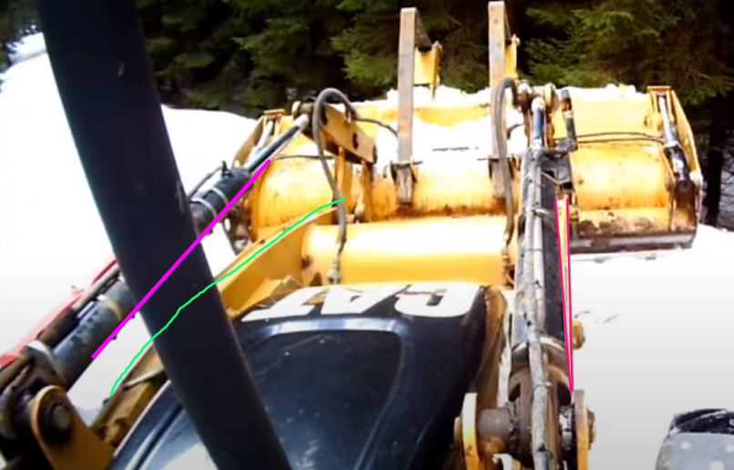
It’s definitely a conundrum trying to determine this without an explicit blueprint / orthographic drawing. BUT in the end, you’re the expert when it comes to these parts. Introducing angles in a mechanical model like this can have consequences if it turns out to be wrong. However sense you’re already mechanically testing how these parts function, you are the only one qualified to make the final call!
I trust you 100% sir 🤝
June 6, 2020 at 1:41 am #56846Have you ever worked on something all month and you feel like it looks really similar to when you stsarted? Man I feel that way right now.
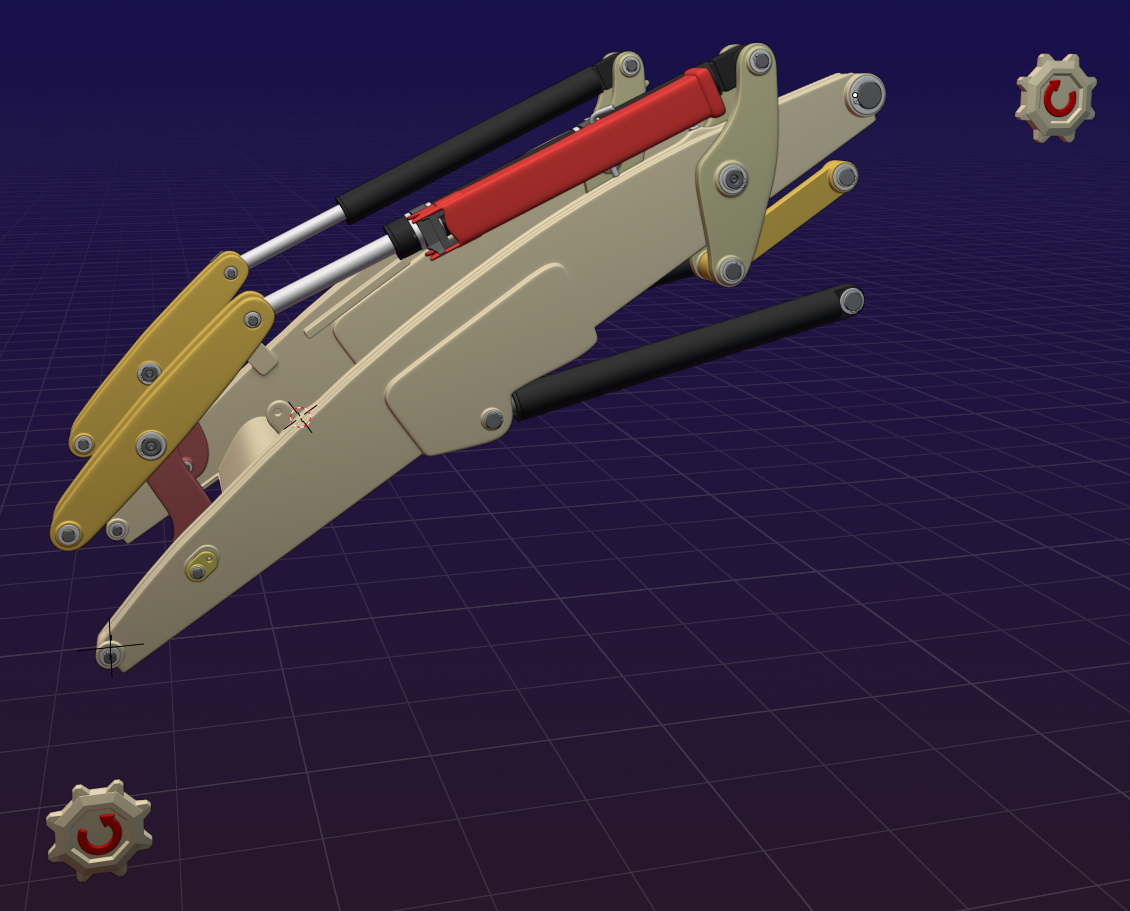
I did a lot of cleanup on the main loader arm and added a lot of details,; corrected the angle bracket issue, figured out rigging to help with seeing issues with the model, and made some cool rig-helpersthat constrain to only somewhat realistic rotation. But at the end of the day I look back and feel exhausted with little visual progress.
Regardless I am happy with it and have uploaded the model.
 June 6, 2020 at 1:53 am #56847
|Have you ever worked on something all month and you feel like it looks really similar to when you started? […] little visual progress.
Yep, I can totally relate to that!
Looking great Shawn!
June 6, 2020 at 4:19 pm #56848Okay I need some guidance because I want to get this resolution before I continue on, there is going to be a lot more interacting on my assembly after this point: Kent is right to be nervous about this hydraulic and angle bracket issue. I want to make sure I get this right by everyone before I make things more complex.
I posted the issue in a YouTube video. Can y’all watch it when you get 3 minutes and let me know your opinions?
I have already made a decision but I have things parented to empties so going the other route won’t be terrible. I explain my decision in the video.I’ m going to @ mention the team below just so The Pound can give feedback.
@pfbourassa @jakeblended @ketre @ullreym @hellosudeepsingh @ryzen7 @doulos4iesou @artifact @adrian2301 @spikeyxxx @duerer @shanr @dostovel @az93 @theluthierThanks for the feedback and critiques.
June 6, 2020 at 4:52 pm #56849I just watched your youtube video: https://www.youtube.com/watch?v=Dzom2msSrBw
That’s a tough one. Something about the pistons being off-axis seems really wrong to me. Like, would the mechanics still work if they weren’t aligned?
Would it work to shift the top connection (closer to the engine) towards the inside so that it would line up again?
It seems like these parts need to be parallel for the same reason the tires need to be parallel. If they are bowed toward each other, rotating them would cause the arms to move closer or further apart, rather then staying the same distance. Right?
June 6, 2020 at 5:17 pm #56850I am not sure if I understnd the problem correctly, but I think I agree with Parker @pfbourassa , imagine this in an extreme situation:
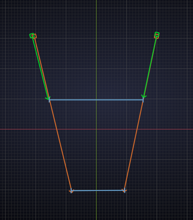
When the green hydraulic cylinders are not parallel and extend into the red arrows, what they are connected to (blue) would be squashed..
I’d say they must be parallel…
Like I said, I am not sure if I understand what’s going on…
June 6, 2020 at 5:35 pm #56851Just found this front view
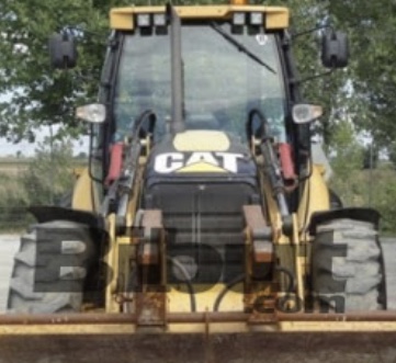
I agree the arms and pistons need to be parallel to function correctly.If you look close, zoom to the top arm from the piston to the bucket, to me it looks like a thin piece on one side of the piston.
June 6, 2020 at 5:47 pm #56852had another look at other images and they all show as you have it. Maybe as suggested by @pfbourassa the top of the piston slightly closer to the engine, so they are parallel but maybe not exactly above the lower arm. It’s so difficult to see, need an up close and personal look.
June 6, 2020 at 6:48 pm #56853Definitely straight

-
AuthorPosts


- The topic ‘Backhoe Contribution – Blanchsb – Exterior Loader Arms and Interior Chair’ is closed to new replies.