
Jake Korosi

Forum Replies Created
-
AuthorPosts
-
Water pump, fuel pump, and harmonic balancer done.
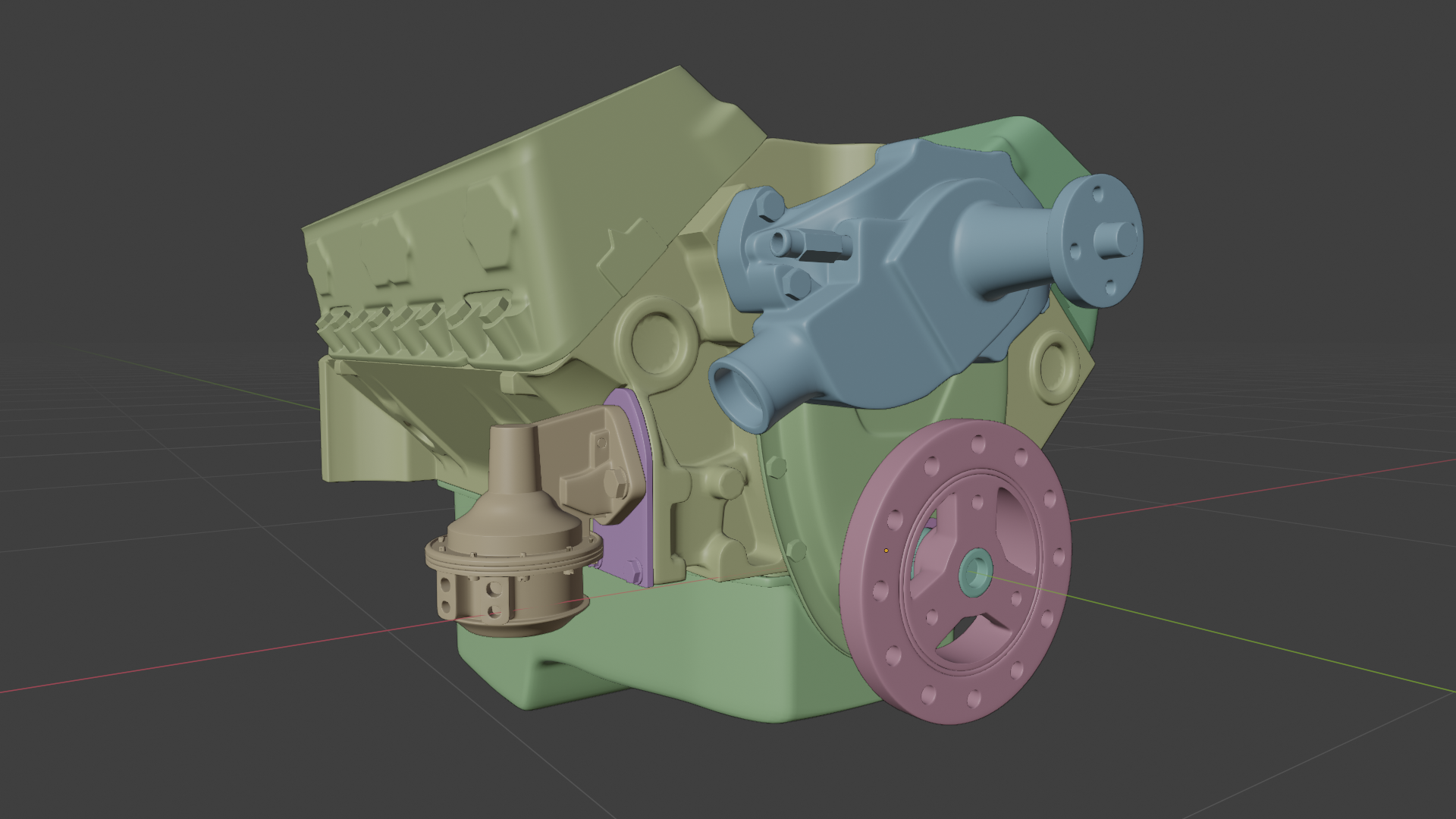
The harmonic balancer is the pink thing fixed to the end of the crankshaft. For such a simple-looking part, the intricacies of what it does and how it works are a little complicated. The simple explanation is that it absorbs and dissipates potentially harmful vibrations from the crankshaft that occur because the engine’s firing order and the weight of the working parts aren’t precisely mathematically 100% perfect. But can we just take a moment to appreciate how cool the name “harmonic balancer” is? It sounds like something that belongs on a spaceship. Like I can imagine Geordi LaForge talking all “If we just reverse the polarity in the harmonic balancers, we can create a warp bubble that will repel the tachyon field!”
Also, the whole time I was modeling the water pump, I kept thinking of that song “Lollipop” from the 1950’s, except every instance of the word “lollipop” in the song was replaced with “water pump”. It really got stuck in my head. And now it’s stuck in yours, bwahahahahahaaaa!
I think the intake manifold will be next. That’s gonna be one tough part to model; you’ll see why when it’s done.
Here’s the thing with all that – with MANY Huion tablets, it does work that easily. By bad luck I happen to have a Q11K model, which was an especial pain to get working due to the manufacturer not correctly assigning the device ID in some way – I haven’t been able to figure out the exact nature of that issue, other than its effect on the tablet being read by the system. Unlike most Huion tablets, when listing devices detected by xsetwacom instead of showing up with the manufacturer name “HUION” it returns the name “TABLET” – yeah that’s right, it’s a “TABLET tablet”. That may sound like a trivial problem but it seems to be the root cause of all of my headaches. Compounding the issue was the fact that there is a “v1” and a “v2” of the Q11K, the fix for each of which was slightly different.
The incompatibility seems to have been fixed a couple of years ago – drivers for the Q11K were added to the “digimend” tablet driver plugin, which allowed non-Wacom tablets to be detected by Linux’s xsetwacom program. That would have fixed the problem. but….
At some point AFTER that fix came out, new drivers were added directly to the Linux kernel itself to “support” several Huion tablets including the Q11K. The new kernel drivers make my tablet basically plug-and-play – I can sculpt in Blender with it, it reads pressure sensitivity, etc etc – HOWEVER, again this particular tablet seems to be in a very special spot because Linux detects it and lets it work as a tablet input as you would expect but I can’t adjust its settings in the tablet panel because for some reason in the device settings, it is listed as a game controller!
Yeah.
I’ve made a few attempts to try and apply the digimend fix, but I haven’t had much success yet and at least one attempt (that I had to recover from) made the native kernel driver stop reading the tablet input completely, so at this point I’m kind of at a stage where at least it’s working and I don’t want to mess with it anymore, at least not until I get through my HUMAN project, after which I might try figuring the mess out again. Luckily enough it already does treat my pen buttons as RMB and MMB – although by preference I prefer to swap which pen button is which -MB. But I can deal with that. I PROBABLY can still set the tablet settings via a Bash script – I read about doing that during my research into the problem – I just haven’t taken the time to do that yet.
So that was a fun little break, but – back to work! This thing’s not going to model itself, you know.
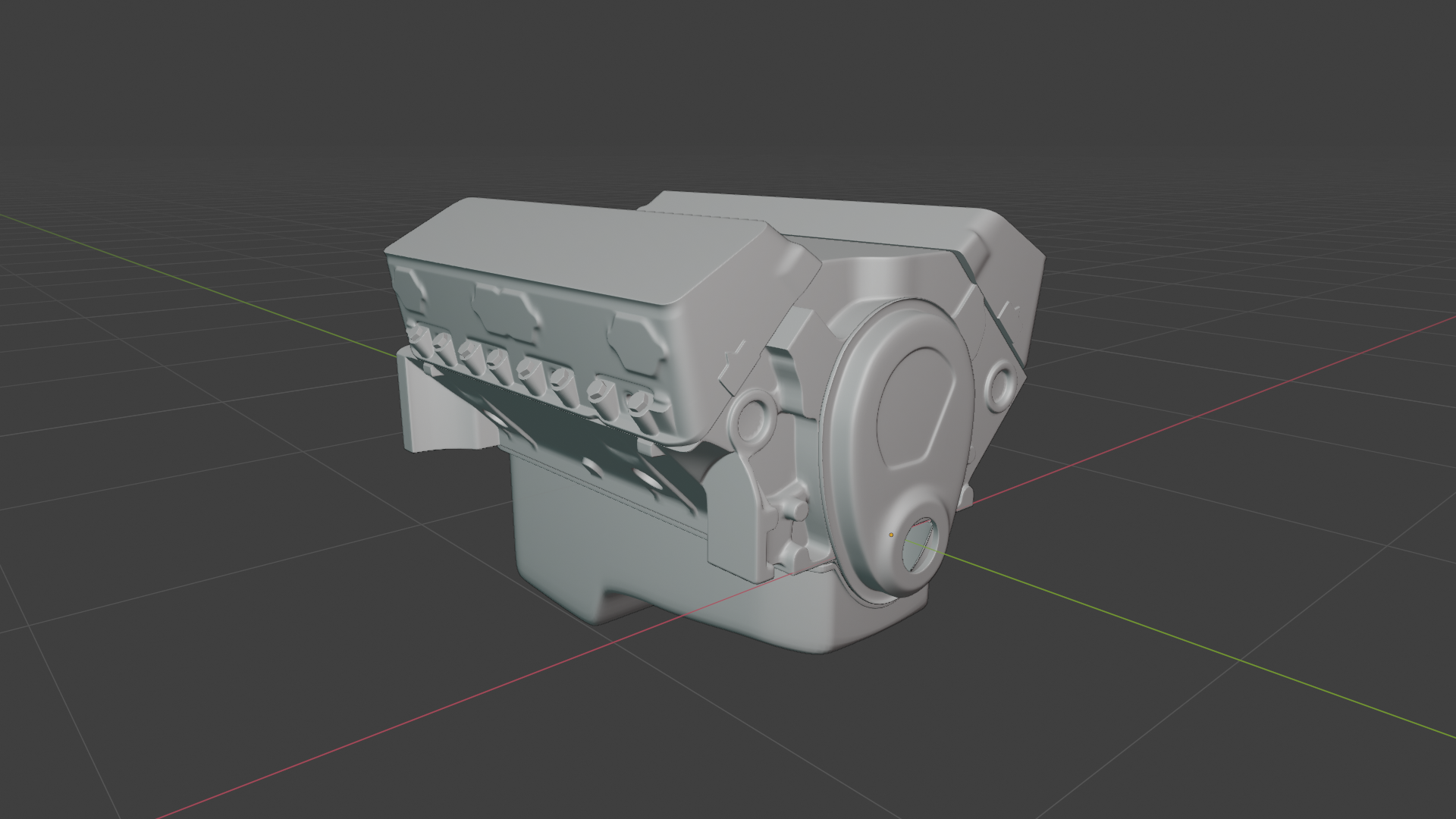
I’ve got the cylinder head finished out and duplicated – not mirrored; the two cylinder banks of the engine are offset slightly along the Y axis, so it was a matter of duplicating the head, rotating it around the engine’s Z axis, and then giving it a little nudge to get it exactly in place. I am lucky at least that the cylinder head itself IS a duplicate – I mean, in “real life”, it is literally two of the exact same part-number. So it’s not even cheating, to make a copy in this case. 😀 Linked-duplicate, of course, so any future edits will apply to both.
Also did the timing chain cover, most of the oil pan, and gaskets for all of these. It’s kind of funny – compared to the rest of the engine components the oil pan is almost jarringly plain and lacking in interest; but that’s really just how they are, unfortunately. At least on the other side there’s a drain bolt (that I still have to put in) to break up the bland.
The next components up after the oil pan are the water pump, which mounts kind of across the front of the timing cover, and the fuel pump, which mounts to that sorta house-shaped flange on the near corner of the engine block. The fuel pump on this engine is mechanical, operated by a pushrod from the camshaft. If you look closely you can see the shape on the front of the engine behind that flange, angled slightly upward toward the middle of the block (where the camshaft would be), where the passage that would accommodate that pushrod is cast into the real thing.
I’ve been taking @theluthier‘s advice about the HUMAN course and previewing the whole thing at 1.5x speed. I’m getting near the end, and as soon as I do I’ll be starting for myself – I DID get my tablet working well with Linux and Blender (although Huion not offering a settings app for Linux means some features are inaccessible like an easy way to customize the buttons, but that’s okay). I’ll be splitting my time evenly between that project and this one, so expect updates for my HUMAN project to be interspersed with updates on the car.
Digging the course, by the way. Even just watching the entire process from beginning to end in the course, the results are already feeling more accessible to me. One thing I love is how way back in his earliest courses on the face and the body, Kent is so self-conscious and uncomfortable using even one or two “technical” anatomical terms, but in this course it’s his zone now and he owns it, ha.
That’s pretty darn good! The retopo is on point.
GO GO GO, Shawn!
You may very well be the first to complete a HUMAN-course project after all!
I’ll be watching and rooting for you. 🙂
@theluthier Haha – thanks! The encouragement from you and the others posting here really means a lot!
I have DREAMED of seeing an assembly animation for this thing. I have a definite look and style visualized inside my head for it, even.
But while I’m confident I can create this model and get some fantastic stills out of it, I would love the challenge of building an animation even, I have to admit that RENDERING such an animation is probably out of the practical reach of my hardware.
Might be a good opportunity to dust off and use some of those Sheepit credits I’ve built up. But would they even be enough? I really am not sure.
It’s a down-the-road thing, at any rate.
Oh yes, don’t worry about that! This specific project is one I’ve been wanting to do since I started learning Blender, and have been saving it until I felt I was ready to take it on. Now that it’s underway it’s not going to stop!
With the Linux….yeah, ha.. The way I’ve heard it, depending on what you want to do on it of course, Linux can be an almighty pain to get fully set up and running but once it’s done, unless you make any really big system changes it’s pretty smooth sailing. Well, I’m leaning toward that being true, because the first half has so far proven pretty accurate…
It’s nearly there though, I think. I went with Kubuntu, just because the UI is extremely Windows-like already in its look and behavior and I didn’t want to have to add acclimating to an unfamiliar UI on top of everything else I was already going to have to do. I like it well enough so far I suppose.
I will say this much. I’ve always thought that the whole Blender vs. Maya vs. 3DS vs. whatever fan-wars were a bit unnecessary and out of hand at times….and then I started looking into what kind of Linux I should try first. It hasn’t ALL been bad, thankfully, but….hoo boy.
Here’s an example of what I mean by finding “some” precise data:
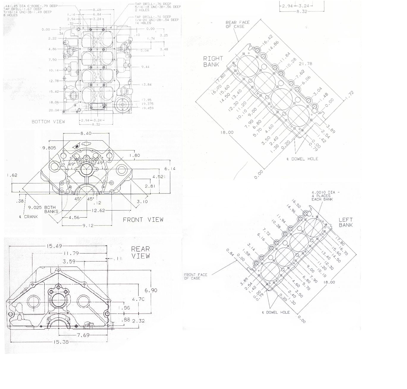
I was able to get or extrapolate some very precise dimensions for the engine block from these drawings, and I used them. MOST of the numbers are for the precise locations of bolt holes, however, and only a few of those measurements were actually useful to me. But, the drawings are orthographic, so I was able to put them into Blender to use as guides to help get my “rough” measurements much closer as well.
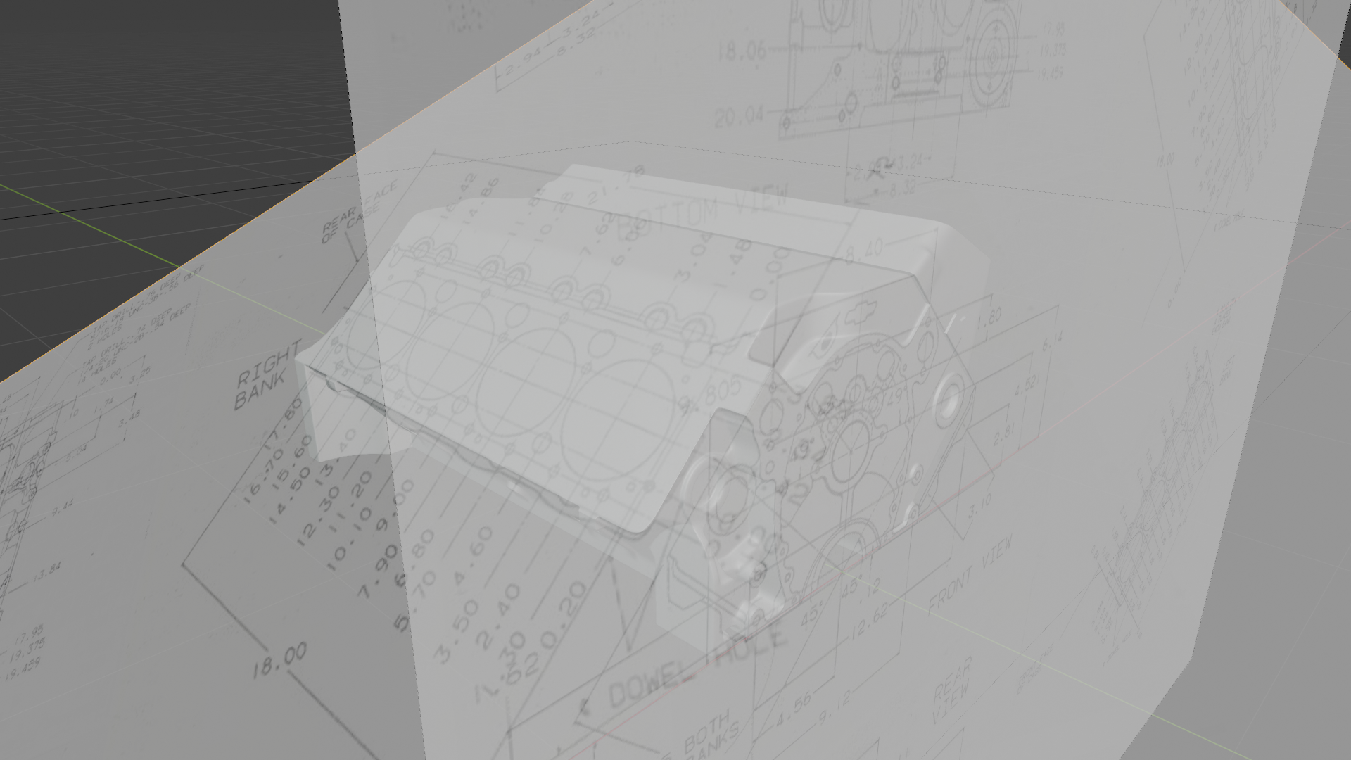
The capability of modeling down to millimeters of precision definitely exists in Blender. The fields that display figures like sizes and locations are truncated and rounded normally, but if you click the field (as if you’re going to edit it) you will see that Blender will accept and be faithful to as many significant digits as you care to throw at it. I dunno, maybe there’s a limit, but if there is, it’s a greater level of precision than you’d ever have a need for. Just for one example – I won’t explain the context (it’d take a while); but one time I modeled a several-kilometers-long object, gave it a very specific curve with a modifier, and verified the verts in the middle of the curve being exactly where the math says they ought to be to SUB-millimeter precision. So yes, the software can do it!
The problem you’re mostly going to have is getting your hands on the data. Where you can FIND the data, you can model as precisely as you want to. But for most things sadly it’s not not available, at least not publicly or easily available; and that is unfortunately the reason why most of the modeling you’ll see in Blender is by eye. If you can FIND a list of CAD-precision measurements for a whole thing, by all means exploit it! But chances are more likely that you’ll find a few very precise figures for some parts of it, and you’ll have to do the rest from the best photos and drawings you can find. So the key is always collecting the best reference you can, and as much of it as you need.
This vehicle I’m making is a little bit more of a “passion project”, I think you could say, than anything I’ve made before. So I really went all out in terms of preparation. For instance, here’s the numbers from my reference folder just for this one single project:

Those are ALL and NOTHING BUT reference images – photos, drawings, and diagrams – for this vehicle that I’ve found online. The amount of reference I’ve gathered for this project beats the next-highest one of mine by around an order of magnitude, ha. It’s kind of ridiculous, admittedly, and the only reason it’s like that is because I knew I was going to be modeling like the complete chassis of this car, meaning that I have to have reference for a lot of components that a typical car-modeling project would just not need.
So it wouldn’t be honest to say that this is my “normal” process. But yeah, I really went in-depth. I found the car’s actual factory assembly instructions, which contained a lot of useful information and measurements. I found photoscans of some of the original promotional material that, interestingly, contained a lot of very precise orthographic cross-sections. And of course, lots and lots (and lots) of photos, from targeted searches. In some cases I went as far as looking up the technical names and even part numbers for some components to get the material I needed, which required a little bit of its own researching. And don’t be afraid to create your own “photos” by skimming YouTube videos to find a couple that happen to very clearly show that one part or angle you just can’t find an actual photo of anywhere, and take screenshots! I didn’t do it all at once, but I think if you added it up I spent a solid week on JUST gathering reference materials. And I’m not even done really; if I’m in the middle of making a certain part and what reference I already have doesn’t cut it, it’s back to the internet to find some more.
I used essentially the same processes to find reference material to share with the group for the DOG backhoe collab project, if you’ve looked into that.
If anyone’s curious, I haven’t given up on this project, I’ve just decided to try out Linux and getting all of my stuff set up and working has been taking most of my time over the last week, heh I want to get it all done before @theluthier‘s HUMAN course launches. Once the system is set up to my liking I’ll get back to working on this for more than just a few minutes at a time.

Engine block is done for now.
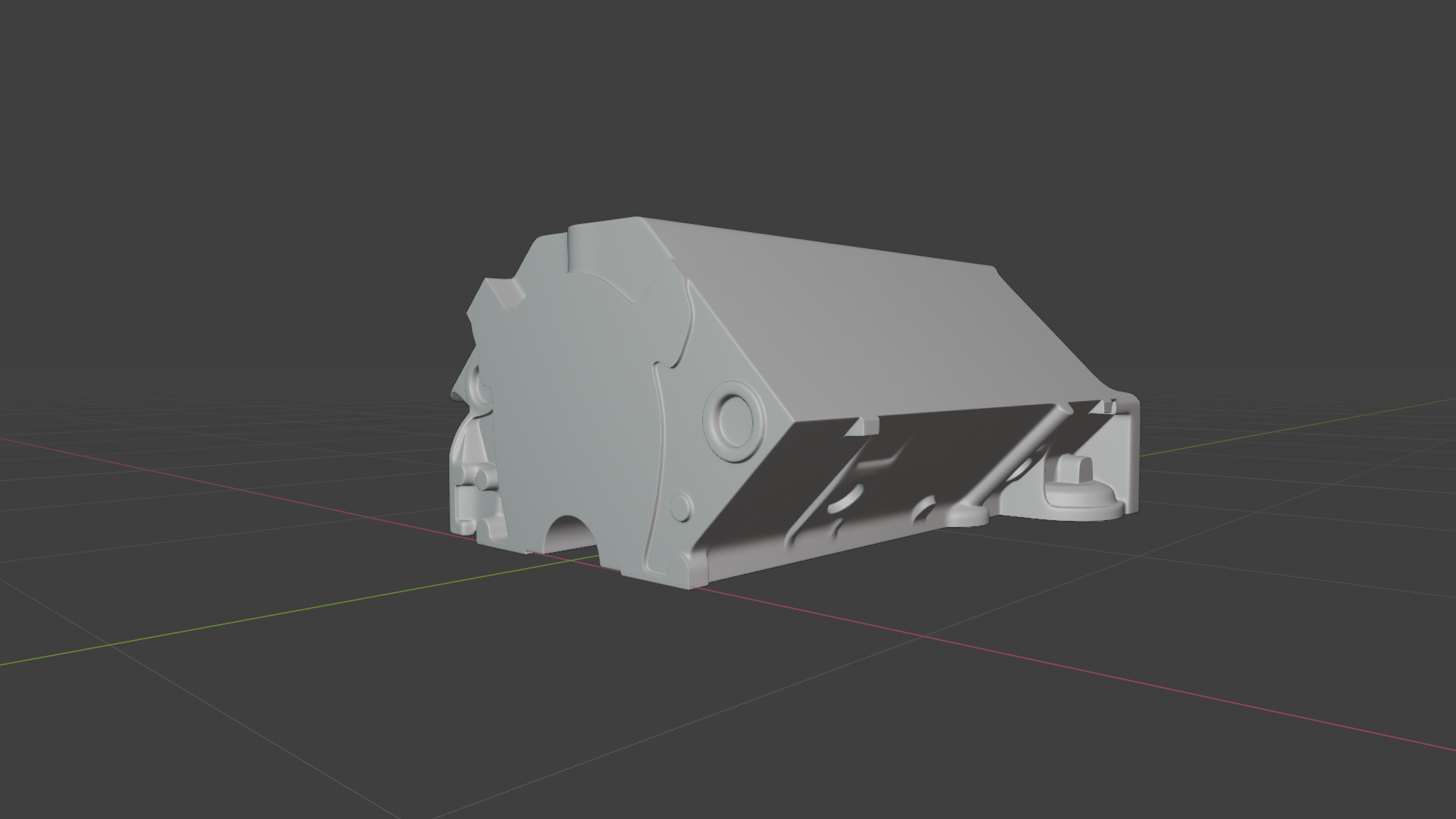
As I predicted, and as you might imagine, you begin this mesh with a fairly simple and symmetrical hexagonal shape; but once that very initial “blockout” is done in the first 5 minutes of building the model, that’s the end of anything simple OR symmetrical. Even the two lateral halves of the block are actually offset from each other about half an inch or so along the Y axis.
The large flat areas on the front and top – there are others on the other sides – are flanges where other parts will be mounted. If I was planning to render the engine block all by itself at some point there would be holes and other details inside these areas; but since they will be covered, there’s no point in modeling any of that.
Cylinder heads next.
Done with the wheels and visible brake hardware:
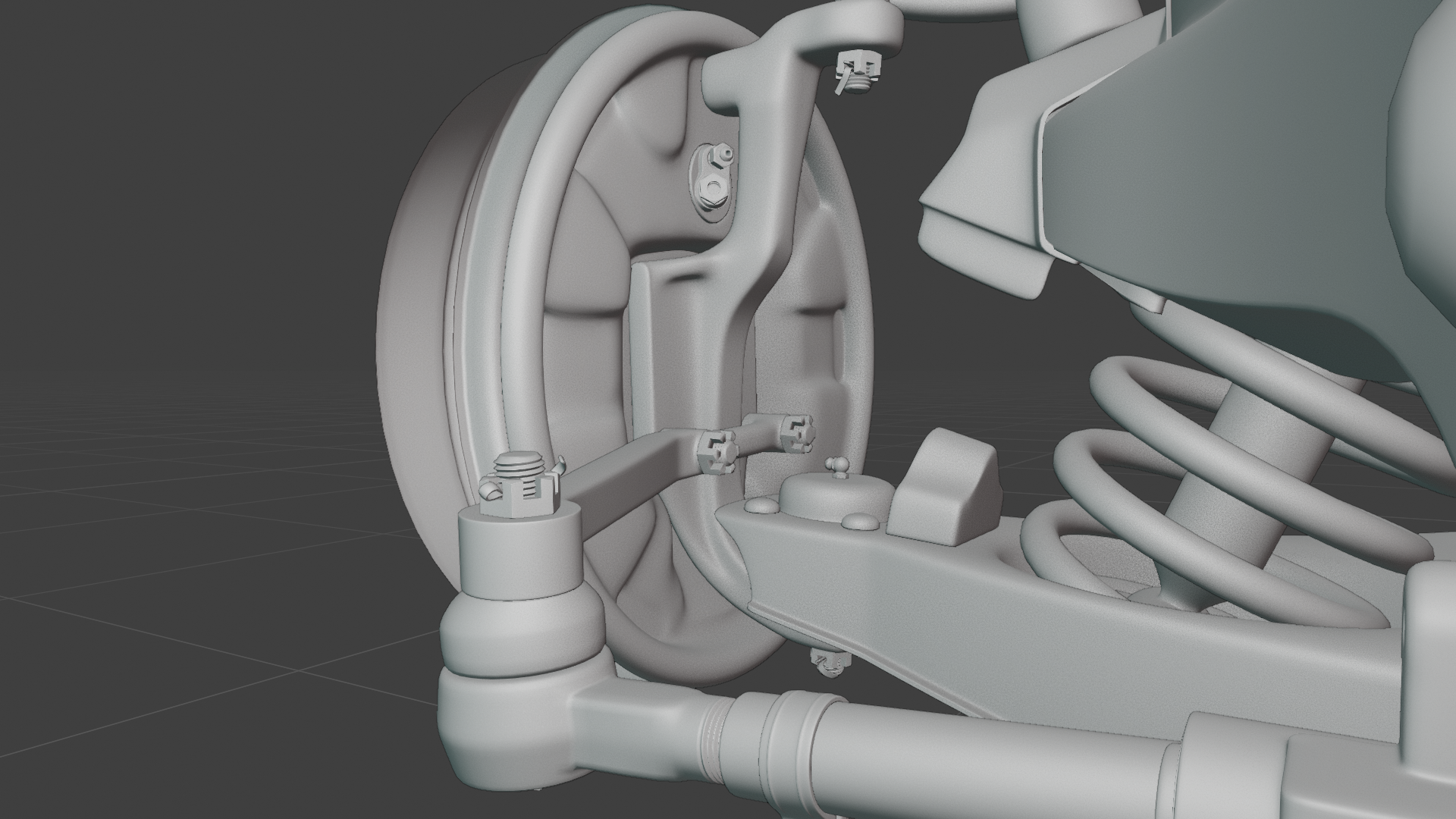
And with that, the mechanical chassis is essentially complete.
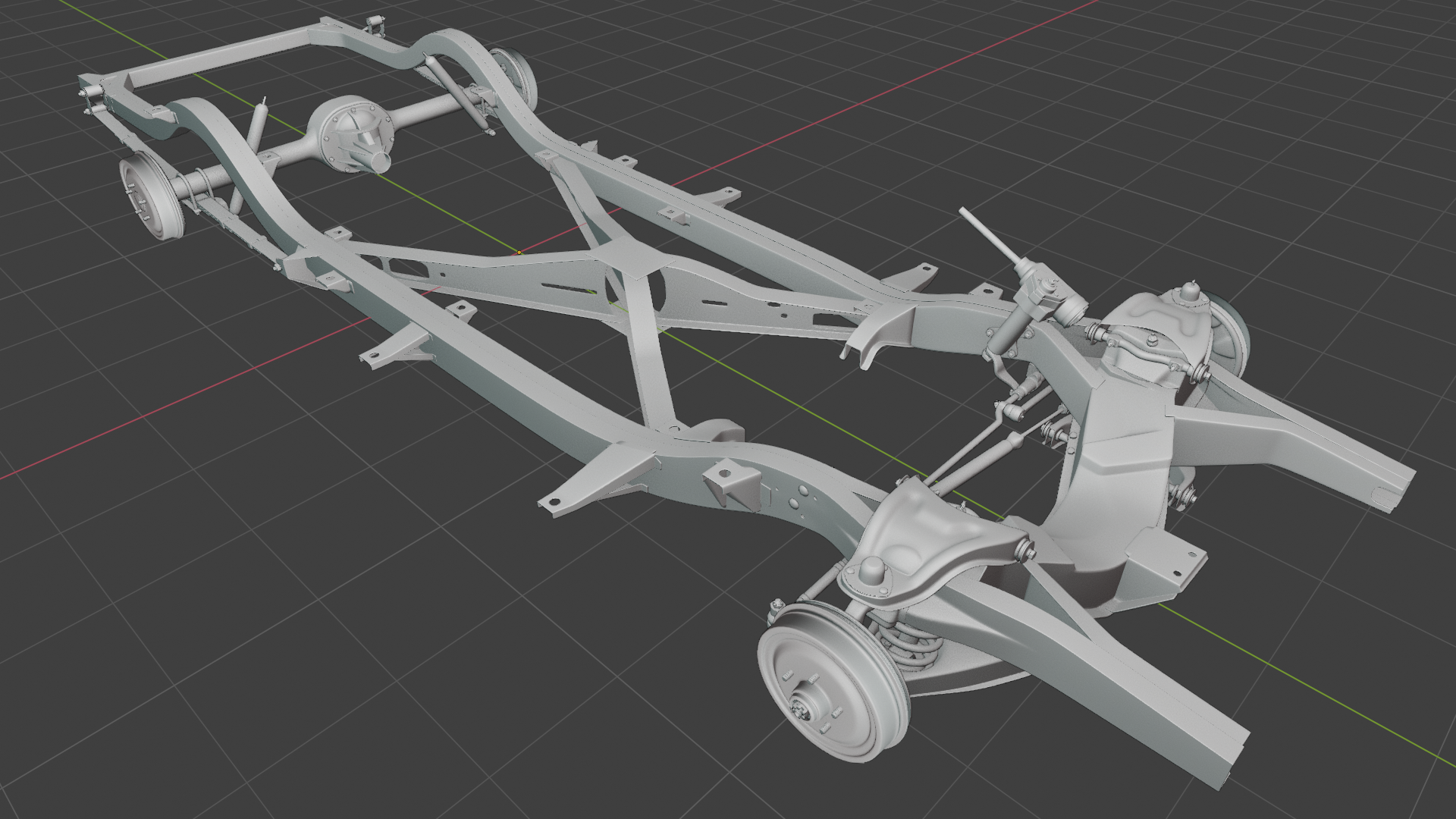
With the wheels, the model has now broken 2M faces! Currently sitting at just over 2.2 million, in fact.
And now….
…now it’s time for Phase 3, the beginning of the Hard Part. Over are the days of nice and mostly-symmetrical, mostly-axis-aligned components and surfaces. It’s time to build the engine.
I have a feeling this will take a bit of a while, so I’m probably going to have to make little progress reports instead of just making one post when the system or section is finished. We’ll see how it goes.
Right now my goal is, I think, to have at least the engine itself and everything immediately attached to it finished by the time HUMAN comes out at the end of next month. I think I can do it in a month. I won’t be too upset if I can’t meet it, but that’s the pace I’m setting right now at least.
Logically, the first components in line are the engine block and cylinder heads. Since the project is now north of 2.2 polys, I’m going to put the engine in its own project file, and also start a separate “Main” project file to link these collections into.
Still a month to go….arrrgh! Hurry up, calendar!
I think I’ve mentioned this before, but I’m already highly impressed with this course just based on few excerpts you’ve teased on Twitter and in the trailer. Tutorials on YouTube about sculpting human faces, even nice ones made by highly talented artists, aren’t rare; but they’re usually short, and they’re almost universally short on theory, usually having you find some reference photos on the web to serve as a template. And there’s nothing in the world wrong with using templates of course – but I’ve always been interested in ideas like proportions and forms. They are things a lot of people tend to neglect or even avoid because of a perception that they are a stodgy set of “rules” that limits your creativity. I tend to think the opposite; I think templates are actually limiting, when you’re trying to invent your own character. If you add a mass to the mesh in “this” area just because the template you’re using shows it there without knowing what exactly it’s doing there, you won’t know what you can change, in what way or how much, and still achieve a result that looks natural. Maybe not a big deal if stylization is your goal; but for photorealism, if you want your character to “look like” a real human then at the very least it needs to be shaped like one.
Until now I’ve always had to look up 2D drawing instructors to learn about things like these. But when I saw the clip you posted where you start building your base mesh using Loomis-style proportions, I was immediately excited. It’s the stuff I’ve been waiting for!
Now someone else needs to spend two years researching and building a course like this on the rest of the body!
Chassis steering done!
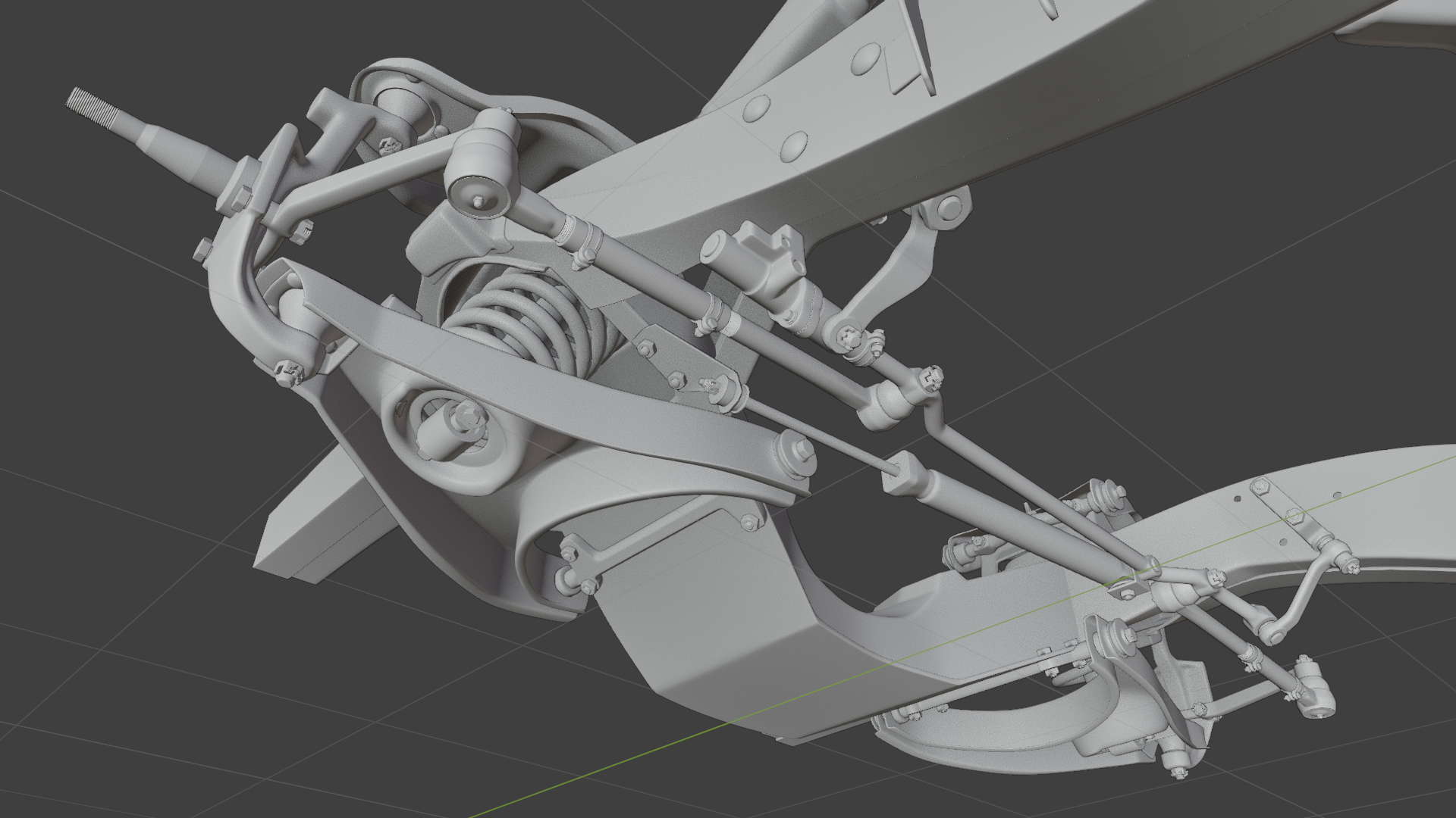
Another angle, with the frame and suspension removed for clarity:
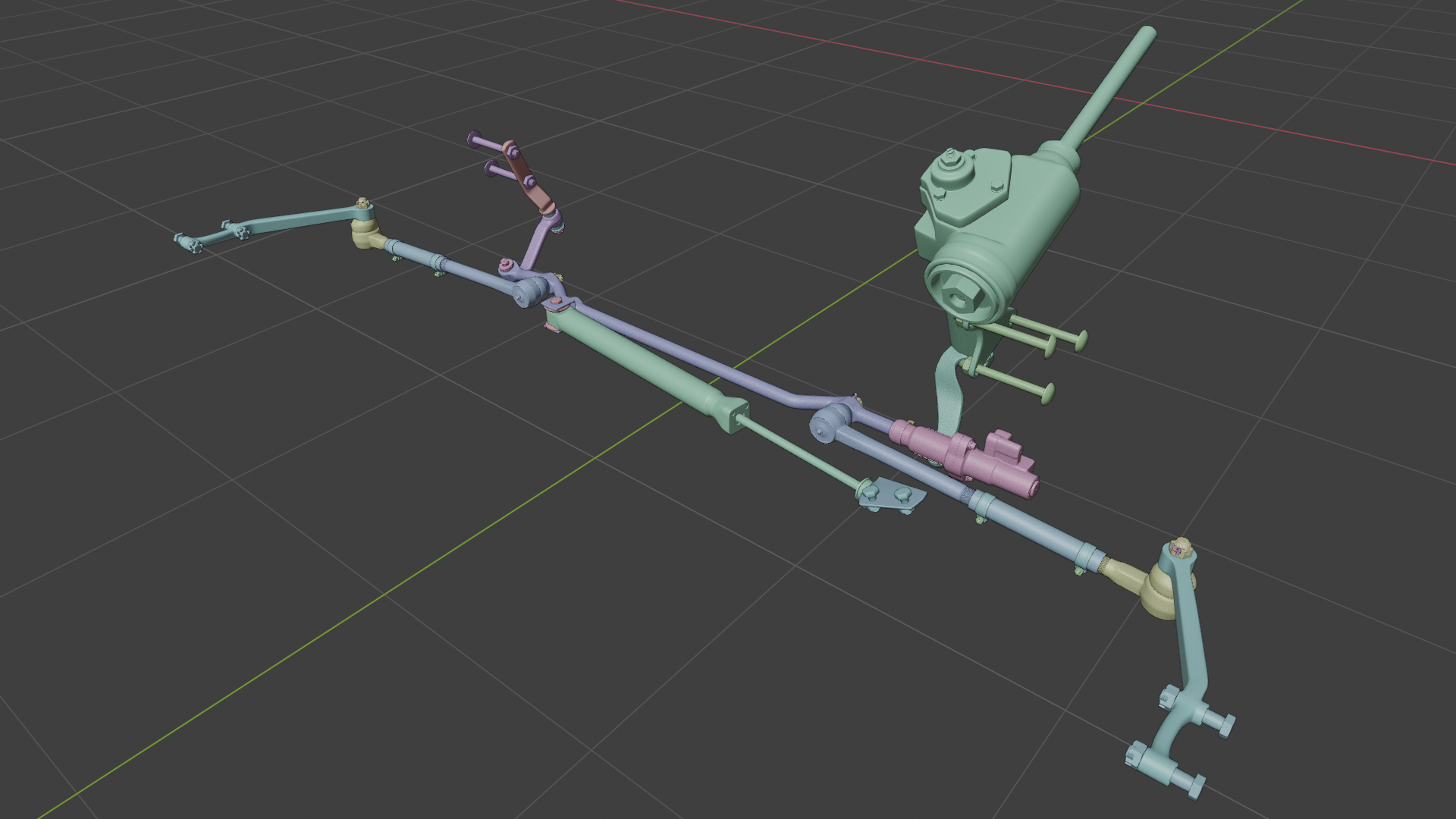
A lot of little parts, with some complexity. This is an older style Pitman or worm-sector steering arrangement, which I suppose makes sense since this is an older vehicle, heh.
It’s also going to have the power steering option, and that’s why you see a few extra components that might not immediately make sense to you, like that hydraulic cylinder right in the middle – this is when power steering on consumer vehicles was a relatively new thing and was somewhat rudimentary compared to the modern-day setup. The way it worked was, the steering gear (big green thing on top) is connected by a lever to a hydraulic control valve (the pink thing below it), which mechanically detects when the driver is having to use an amount of force over a certain limit – around three pounds, according to the features brochure – to turn the steering wheel. If that is the case, the control valve sends hydraulic fluid through a pair of hoses to either push or pull a ram cylinder (green thing in the middle), which helps move the steering mechanism, saving the driver some effort. A second pair of hoses connects the control valve to the power steering fluid pump, which is attached to the engine of course. I haven’t modeled the hoses yet, I’m going to make them along with the pump when I build the engine, which I’ll be starting on not long from now.
But first, I’m going to model the wheel hubs and brake components (the ones that can be seen, at least). That shouldn’t take long at all – just a handful of nice simple parts to relax on before I start on the engine, which is going to be pretty intense.
I have a nagging urge to try rigging the steering and suspension. I’m trying my best to ignore it…
Rear suspension complete!
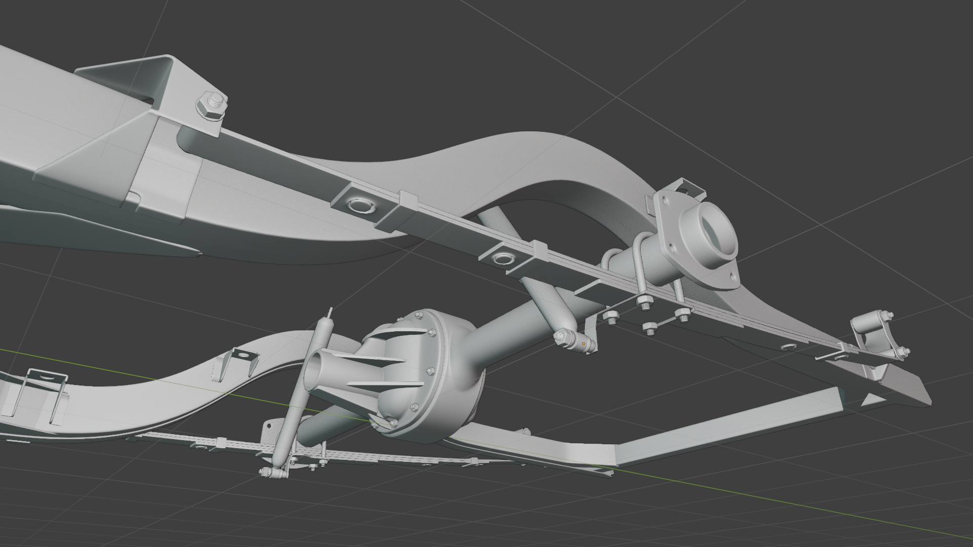
Everything in this segment snapped together fairly easily….except for the differential, that part in the middle of the axle. That was a Boolean Battle. I just couldn’t get nice neat unions and I started over at least four times – that’s what’s been taking this group so long, just that one part.
And I’m STILL not completely happy with it. The joins are neat but not neat enough to bevel easily – even via modifier – and it’s a cast iron piece, it’s supposed to have very wide lazy bevels that make it look more organic, rather than those neat, precise corners. I think I may end up using some sculpting to fill in and smooth all of those edges and then retopologize it – I’m not sure. That’s a task for down the pike though so I’m not going to stress over it now; all of the components are here so I’m going to call it done. The tops of the shock absorbers bolt into the floor pan which isn’t coming for a little while yet, so for now they have to just kind of stick up into nothing, ha.
Next up, to finish out the mechanical chassis I’ll add the steering linkage and the wheel hubs. That will be the end of Phase 2.
That’s when the REALLY challenging part begins…
-
AuthorPosts
