
Spikey’s Math Lab
Forum Archive › Spikey’s Math Lab
- This topic has 137 replies, 8 voices, and was last updated 4 years, 7 months ago by
Omar Domenech.
-
AuthorPosts
-
March 9, 2021 at 9:55 am #13610
Get it? Math Lab…. sounds like Me…. Lab?…. No? ok
So @spikeyxxx you’re like a super mathematician, I’m doing the Blender Cloud Procedural Shading course and it is super heavy dense in tough, difficult and impossible things and worst of all there’s like a lot of math involved. I wanted to use this to bother you a lot and ask you math questions when it comes to procedural shading.
The course is good but Simon goes way too fast and doesn’t get into the really basics and assumes you know what happens mathematically under the hood.
*WARNING, HERE BE MATH*
March 9, 2021 at 9:57 am #64239So to get started I ask you this Spikey, why when I have a plane and I use the Object coordinate (which starts from the object origin) and I get the X component… ok all good…
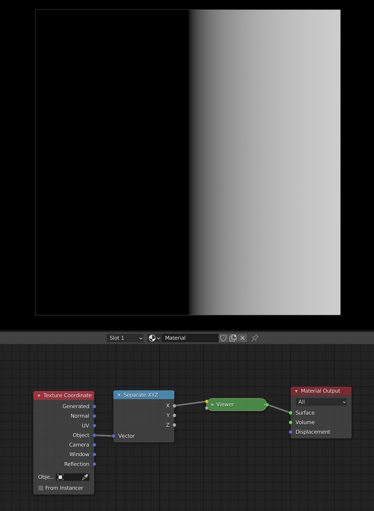
But then I add the Y coordinate and it goes diagonal.
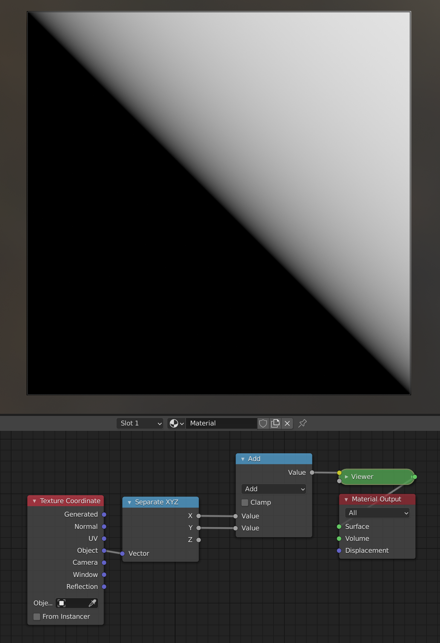
Why is that the behavior? What is going on there? I know I can get a diagonal gradient that way but why does it do that? What math is going on beneath it? Help me Obi Spike Kenobi, you’re my only hope.
March 9, 2021 at 11:34 am #64240When I was a kid, I wanted to become a math teacher…you sort of make my dream come true…thank you!
I will give it a try; look at this picture:
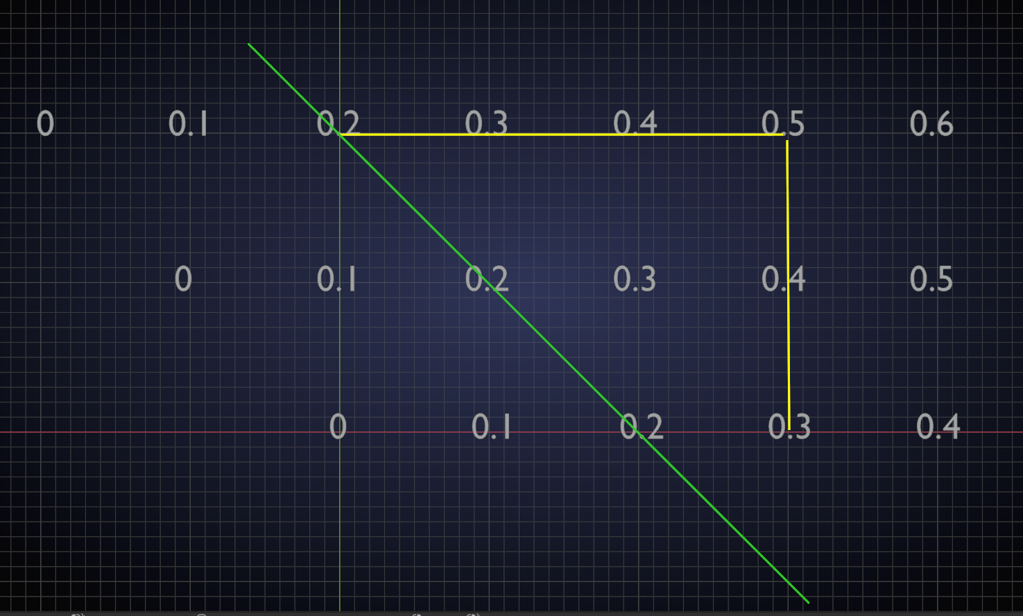
I put in some numbers. Now the ‘points’ in the plane are the number on the X-axis plus the number on the Y-axis. See the yellow lines, where 0.5 = 0.3 + 0.2.
The green line is where all points (x + y) are the same; in this case 0.2. In your picture, where the border between black (all negative numbers) and white is where the sum of x and y is zero.
March 9, 2021 at 4:31 pm #64241
So, let me see if I understand…
I assume that in the plane the black and white gradient, those pixels have a value. Form what I’ve seen in the course, just because you see black doesn’t mean the value of that pixel is zero (0), it’s just that my monitor can only display from 0 to 1, but a black pixel can easily be -5 and a white pixel be 15.
So the numbers you put there on the graph you made, the values of 0, 0.1, 0.2, 0.3, 0.4, 0.5… those can be seen like the values of the pixels on the gradient in the plane. So when I tell Blender with the Separate XYZ Node, please give me the values of X, it goes from one end of the plane to the other, where the object origin is X=0 and Y=0 or (0,0) I guess. So everything left of X=0 is negative and right of X=0 is positive and everything down of Y=0 is negative and up of Y=0 is positive.
When I say, Node, get me the X

And then Node get me the Y
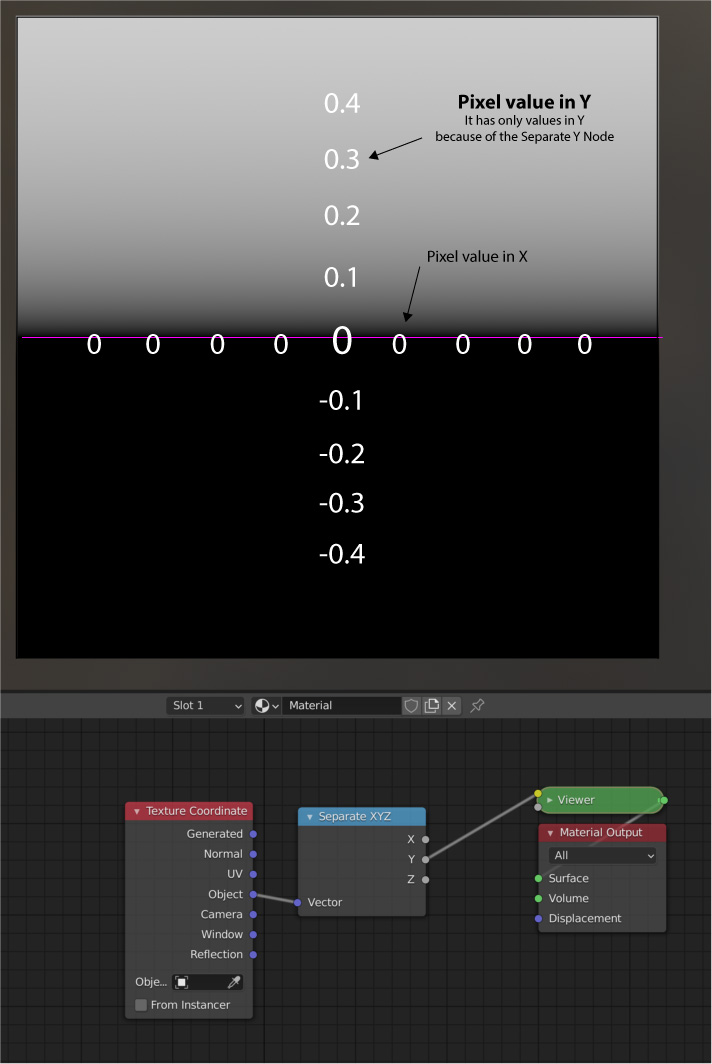
And then….

OH MY GOD!
Spikey, I think I see it. Is it like that? right?
 March 9, 2021 at 4:34 pm #64242
YOU’VE GOT IT!
That is exactly right!
March 9, 2021 at 4:38 pm #64243Thank you Spikey.

Now to try and understand what happens when I change the operation to multiply X and Y. But one step at a time, I’ll get into that after I do some modeling for the TSFHI.
March 9, 2021 at 6:46 pm #64244@dostovel only look at this after you’ve done some top secret modeling!
That is basically the same, apart from the fact that multiplication is a tad more difficult than addition (don’t even get me started on division & Co.):
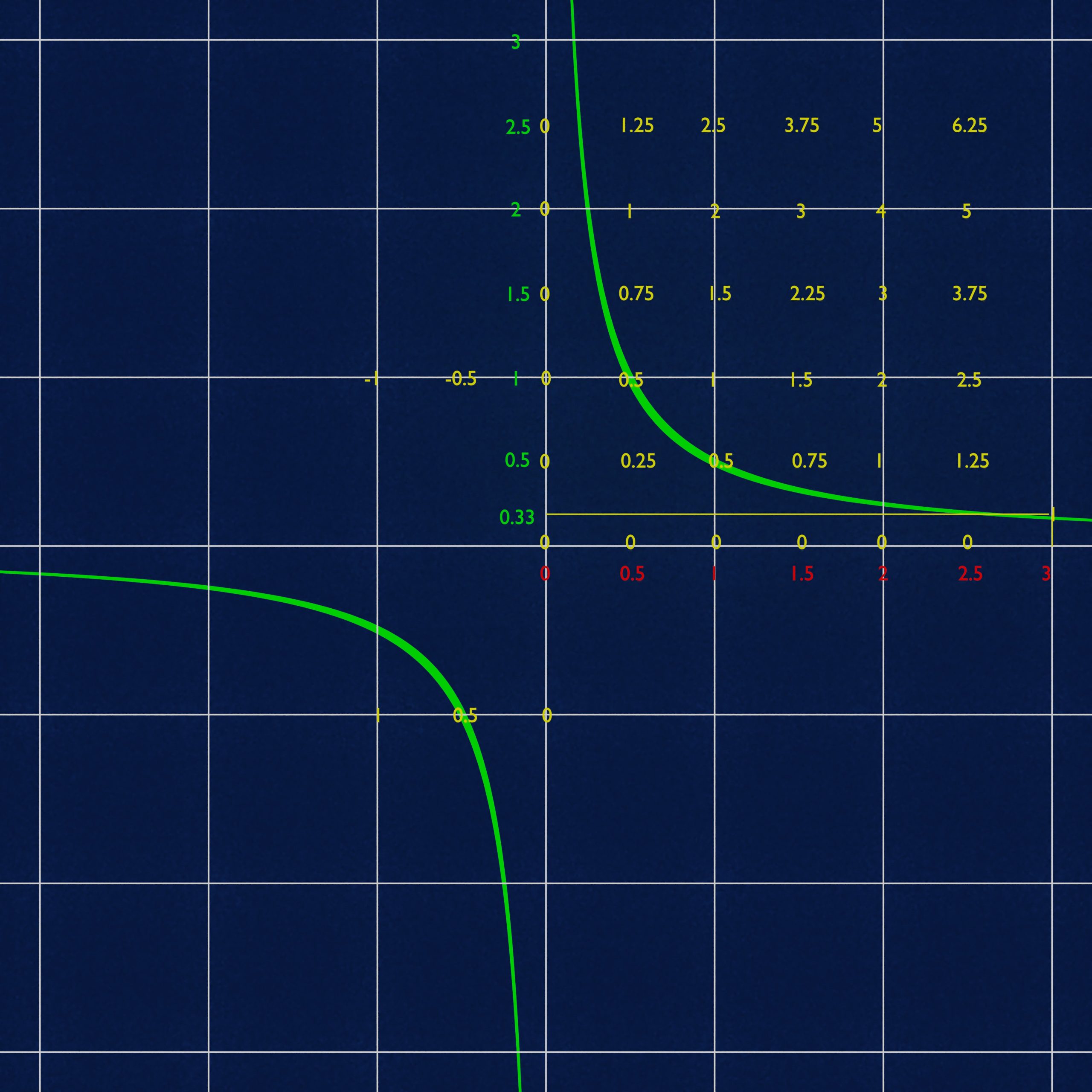
Let me explain what you are looking at here: the red numbers are (some of) the X-values and the green numbers (some of) the Y-values. The yellow numbers are the product of the X- and Y-values and the green curvy thing is where the product is 0.5.
Note that, when you multiply two numbers, that are larger than1, the result will be larger than either one of those numbers and that when you multiply two numbers smaller than 1, the result will be smaller than either one. Nobody knows what will happen when you multiply one number smaller than 1 with one larger than 1,,,
It is also noteworthy, that green times red is the same as red times green (0.5 * 2 = 1 = 2 * 0.5). This is called commutativity by mathematicians, so when you hear someone talk about a commutative ring with 1, you will know at least one third of what he or she is talking about…Sorry, I tend to divert when it comes to math 🙂
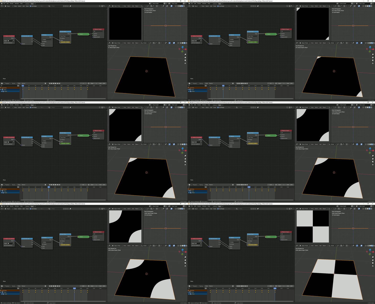
March 10, 2021 at 4:53 am #64245I just created a short animation for the coordinates where the multiplication of “Object X and Y” creates a negative number:
 March 10, 2021 at 5:11 am #64246March 10, 2021 at 5:15 am #64247
@spikeyxxx Handmade with IrfanView (fortunately just 200 screenshots 😉) and then processed in Gimp (Optimization for Gif and then saving as “.gif” with 40ms delay between each frame).
March 10, 2021 at 5:35 am #64248I don’t know IrfanView, but did you know that there is a handy Addon in Blender:
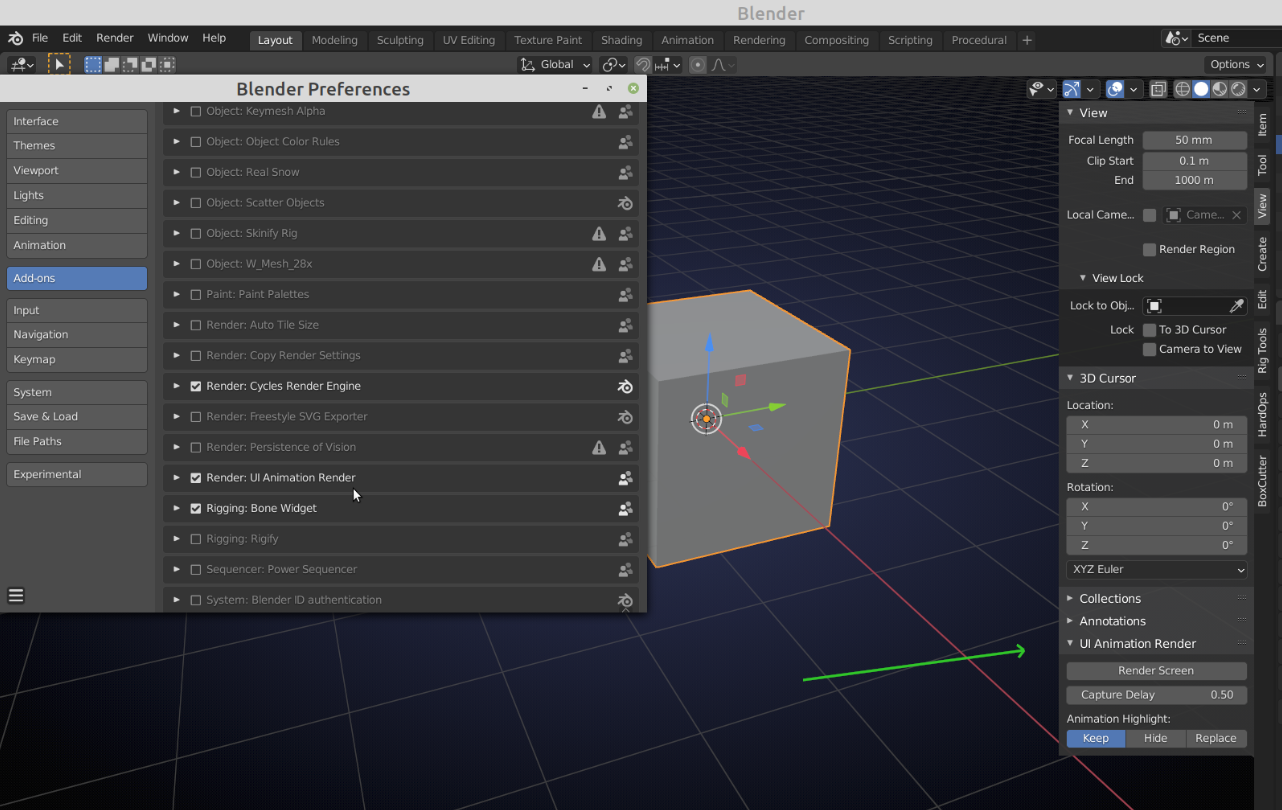
I think it comes shipped with Blender.
March 10, 2021 at 5:41 am #64249Instead of using an “Add Node”, a “Subtract Node” can also be used in order to create a diagonal which is rotated 90 degress around “Local Z” compared with the use of the “Add Node”. It’s also important since although the remapping necessary for the “RGB Curves Node” will work for the “Object X Coordinate” it won’t work when doing the same remapping for the “Object Y Coordinate” with an “Add Node” after this:
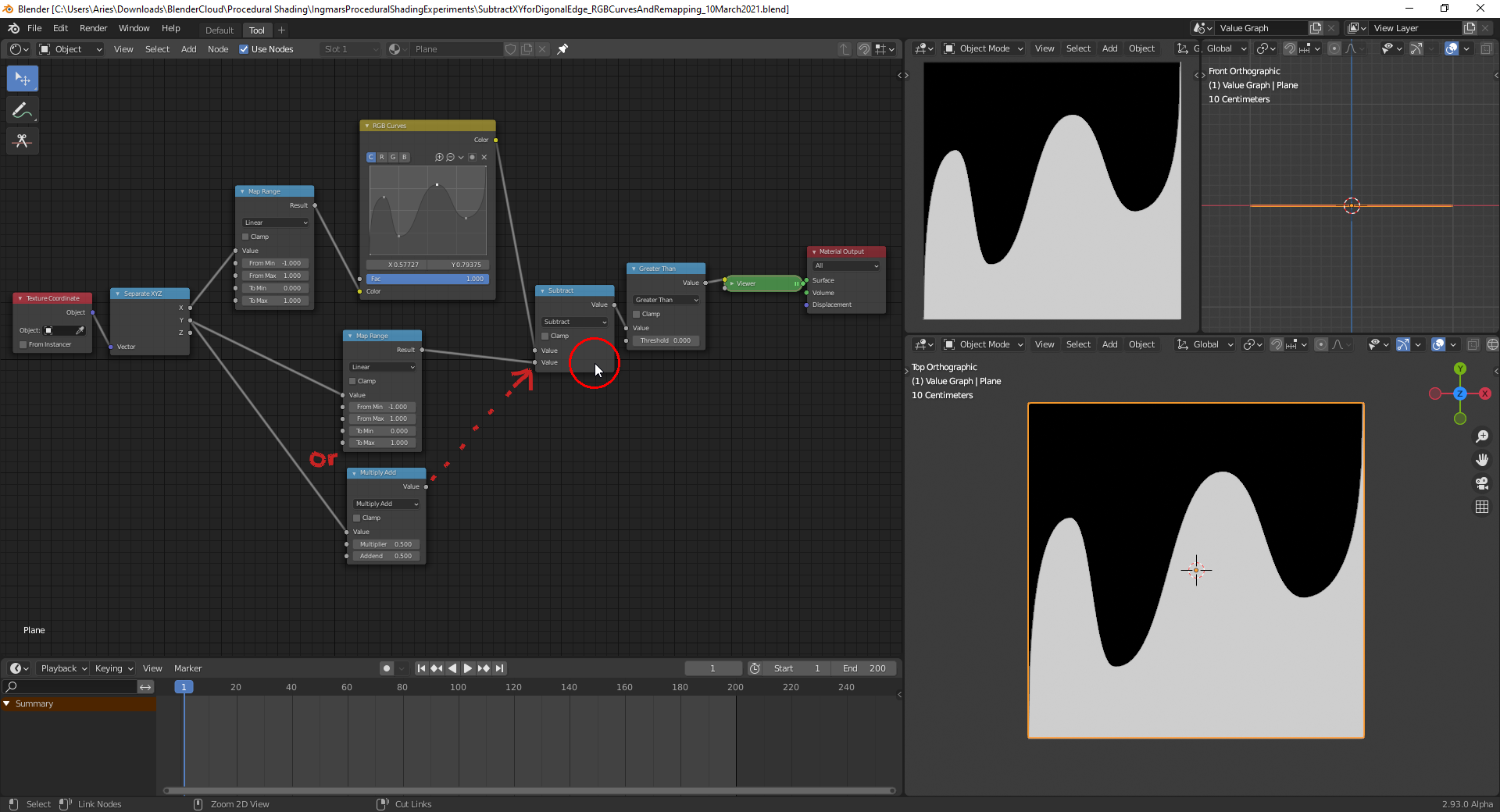
An addition would make everything white when replacing the “Subtract Node” in the node setup above. File is here.
March 10, 2021 at 5:46 am #64250@spikeyxxx Thanks, I didn’t know that with the “UI Animation” addon 😀! Does it work similar to the abandoned “Blender Screencast”? An alternative would be using “OBS Studio” recording and converting it with Gimp and the “Gap” addon into an image sequence but this would have taken me probably more time than doing it manually with screenshots 😉.
March 10, 2021 at 5:54 am #64251@duerer it records the UI whilst playing the Animation (so just like in your GIF) and outputs it into your output path. If your animation is 200 frames, it only records those 200 frames, so you don’t have to cut it or so. A lot easier and faster than making 200 screenshots 😉
March 10, 2021 at 6:08 am #64252@spikeyxxx I’ve just tested the “UI Animation” addon and it works really fine 👍! It’s a hidden gem and definitively worth being recommended! Thanks again, @spikeyxxx 😀!
-
AuthorPosts


- The topic ‘Spikey’s Math Lab’ is closed to new replies.