
Collab 2020: Modeling Heavy Equipment (Backhoe)
Forum Archive › Collab 2020: Modeling Heavy Equipment (Backhoe)
- This topic has 1,439 replies, 27 voices, and was last updated 4 years, 1 month ago by
Omar Domenech.
-
AuthorPosts
-
April 4, 2020 at 12:49 pm #53852
Are the front axle and the back axle identical?
I just used the pictures that were in the file. I know that all wheels are able to rotate from the description and by the looks of it the front and back are the same, just mirrored….
In cases like this, you just have to think about how this would be able to work, look at a lot of reference pictures and don’t trust those drawings too much!
Those rim pictures you got are great!
Your profile of the treads however looks like it is put on top of the tire and the tire is made out of one piece of rubber…
April 4, 2020 at 1:04 pm #53853Yes, I was wondering how this vehicle is driven, but for the heavy work it has to fullfill, I supposed that it uses a four-wheel-drive. My tyre treads have to be reshaped since their outlines are just a very rough approximation. I made them by extruding an edge with snapping “individual elements” on the tyre surface and adding a solidify modifier. The “rubber” look comes from the subsurf modifier. I need to sharpen the tread outlines more after the blocking stage.
April 4, 2020 at 1:05 pm #53854But one more reason to update to Blender 2.83 .
April 4, 2020 at 1:37 pm #53855I don’t know if you can access my file, but this is what my tire looks like without Modifiers:
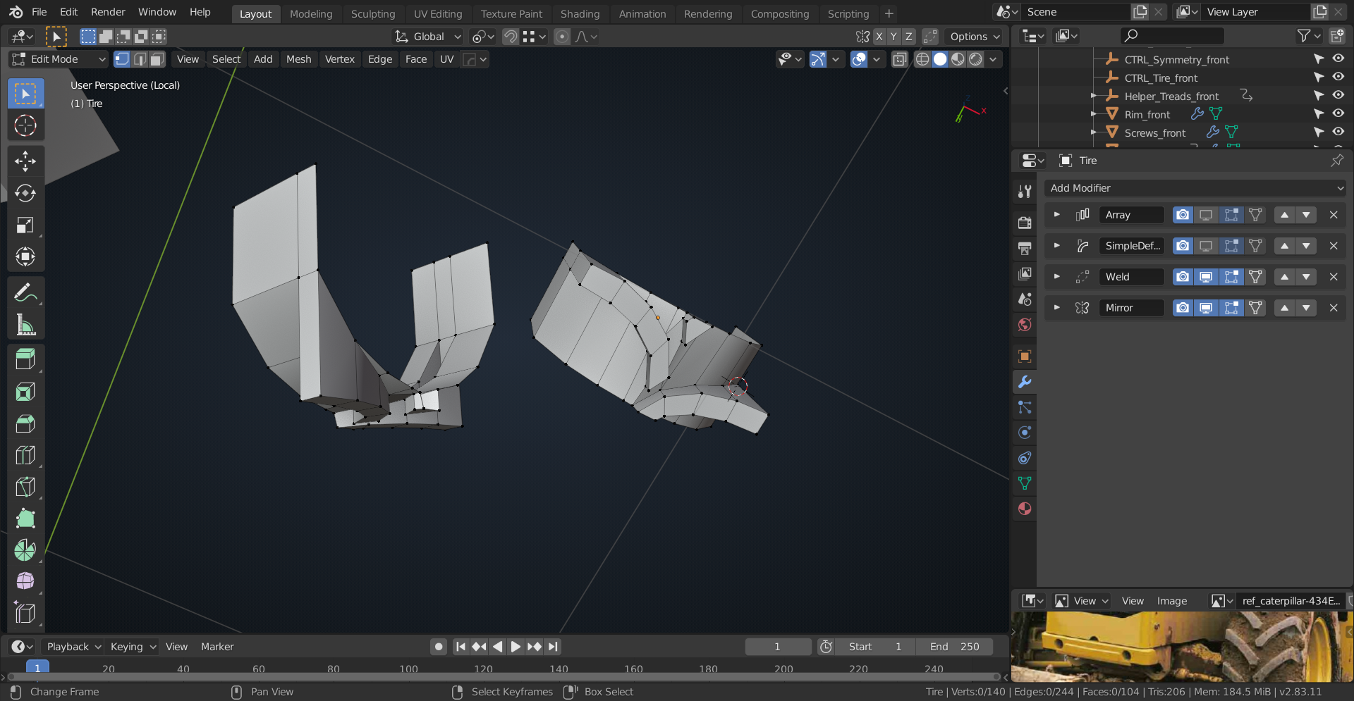
Quite simple and easy to modify, I think.
April 4, 2020 at 2:31 pm #53856This is the first time I’ve used the google spreadsheet, so I don’t know if I got my dropbox link in it or not. Here’s the link in case I screwed something up:
https://www.dropbox.com/s/e5hoau9endftzop/Engine_block.blend?dl=0
April 4, 2020 at 2:39 pm #53857Yes, I can access your file and have also done it with your first wheel version where I especially admired your already complex blocking of the axles. Your approach of dividing the tyre into repeating segments is a clever idea. I also wanted to find a solution that offers the possibility to manipulate the tread pattern easily. The main focus for the treads now is to match the correct shape better. Later, I’ll tackle the transition between the treads and the rest of tyre with a concave beveling so that the treads look like organically “growing” out of the tyre instead of just lying on its surface. There’s also a clearly visible bigger bevel towards the tyre sides. By the way: I’ve already seen 3 different tyre versions by Michelin, Goodyear and Musclerok. I’m not sure whether Caterpillar offers all 3 of them to the clients or delivers the backhoe just with one standard type.
April 4, 2020 at 2:58 pm #53858I started with an Array Modifier with an Object Offset, but in the second version went for a Simple Deform Modifier, set to Bend, because that has a lot of advantages, although a bit trickier to set up. ( Try both methods and you’ll be able to see the differences.)
I think it is important to realize that a tire is one piece and not something welded together, but you know that already.
I’ve seen a ‘live Cat’ that had Michelin tires, but I’m sure that that’s not obligatory.
To be quite honest, the (almost) greatest problem for me in a project like this is the naming of all the parts;)
April 4, 2020 at 3:38 pm #53859I separated of the treads from the rest of tyre only in order to keep as much control as possible over the manipulation of the tread shape without touching the tyre’s main body. Of course, this doesn’t reflect the reality of a real live tyre which is produced directly as one piece. As soon as I’m satisfied with the tread’s shape. I can join it with the rest of the tyre.
For the tyre version: Maybe the official brochures can give a hint which brands are used for newly produced Caterpillars. Maybe they differ from region to region?
For the part naming: I’m sure at the end of the project we’re backhoe experts and open our own factory 😉 . But seriously: It makes fun to find out how thinks work which then helps to create a convincing model that looks like a fully functional backhoe.
April 4, 2020 at 3:53 pm #53860Good job! I would just add the exhaust pipe.
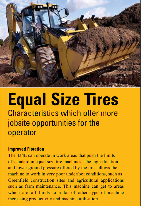
April 5, 2020 at 1:17 am #53861Just as a reminder: don’t trust the drawings too much:
 April 5, 2020 at 1:45 am #53862
This makes things a lot easier if you dont need special settings for the back tyres. I’m just wondering why they publish drawings that don’t reflect the reality and cause even a little bit more work instead of just copying the front wheel.
April 5, 2020 at 1:53 am #53863I guess these drawings are not meant to be used as modelling sheets…
April 5, 2020 at 2:25 am #53864These appear to be a bit more accurate (at least as far as scale is concerned):
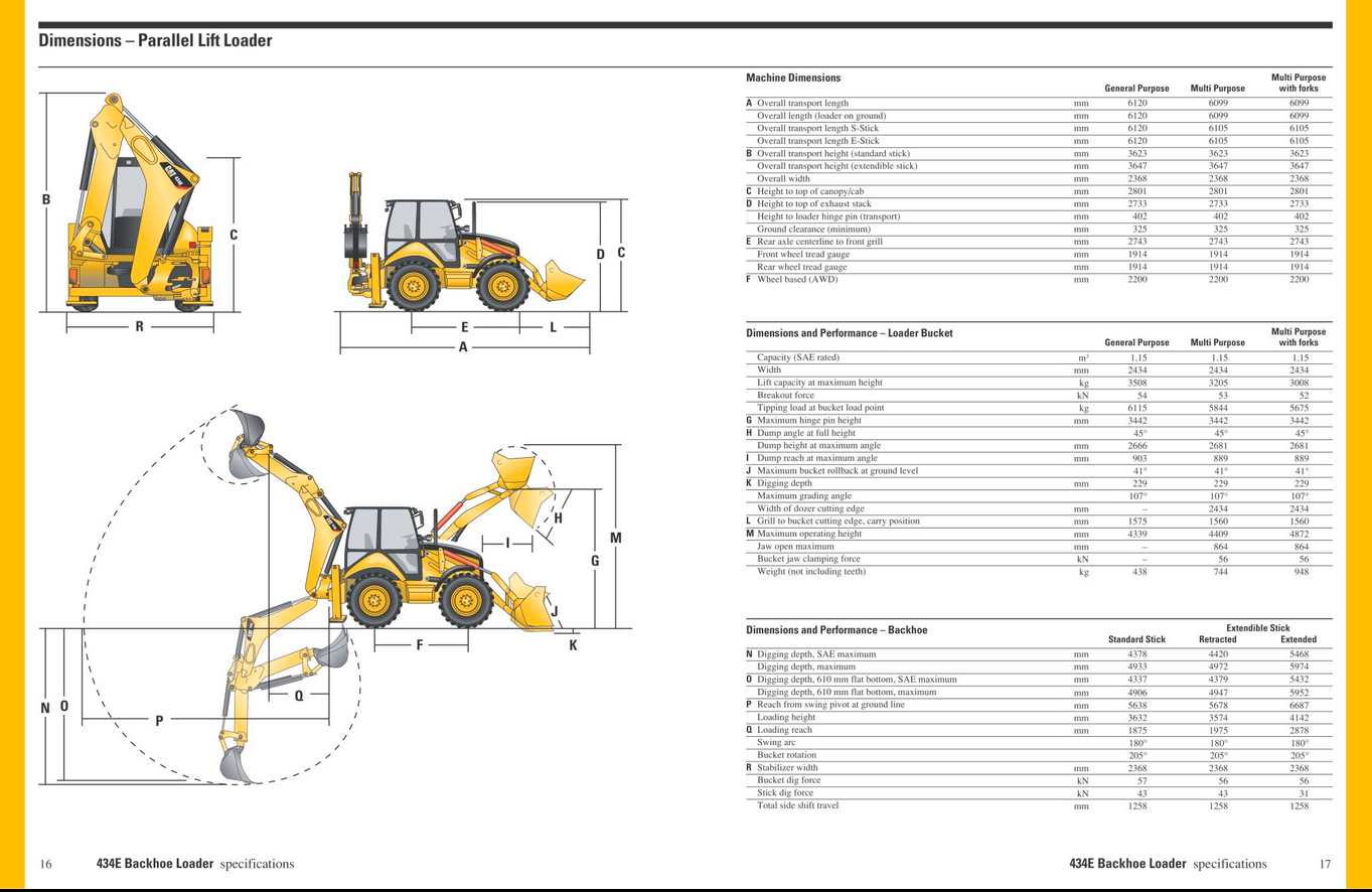
Found here: https://pdf.directindustry.com/pdf/caterpillar-equipment/backhoe-loader/19427-32320-_11.html
April 5, 2020 at 2:38 am #53865I can choose a different part of the blockout?
April 5, 2020 at 3:47 am #53866The lowest image on page 16 in the brochure is a little bit strange: the backhoe undermines its own stabilizer 😉 .
-
AuthorPosts


- The topic ‘Collab 2020: Modeling Heavy Equipment (Backhoe)’ is closed to new replies.