
Backhoe Contribution – adrian2301 – Chassis/Stabilizer/Fenders and the Engine. And the hydraulics for the swing frame.
Forum Archive › Backhoe Contribution – adrian2301 – Chassis/Stabilizer/Fenders and the Engine. And the hydraulics for the swing frame.
- This topic has 134 replies, 10 voices, and was last updated 5 years, 12 months ago by
Adrian Bellworthy.
-
AuthorPosts
-
May 20, 2020 at 8:25 am #56689
Oh yes, way better. Well done 👌
May 31, 2020 at 1:29 pm #56690Man @adrian2301 I never saw this notification, my bad. Bolts need to be hexagonal where they will be intentionally removed for repair/maintenance. They are an industrial standard. The area surrounding the bolt is typically rounded if the material permits such geometry.
Here’s some fun bolt theory:
Most bolt fasteners have a hexagonal head or 12 pointed head just because the sockets used in industry only come in 6 and 12 point (typically haha). 12 point are often used in areas where there is tight space and a wrench does not have a lot of room to turn, and 12 sided bolts have a lower torque rating because the heads tend to strip with more torque. 6 sided bolts can handle a ton of torque but require a decent amount of elbow room to turn a wrench on the. This is why you see open ended wrenchs have their profile bend to some kind of angle. It allows for partial turning of a bolt so you can flip the wrench around 180 and get it with hopefully enough angle from the other side. There are some special wrenches out there that are made by Snap-On and other companies that can handle almost any bolt orientation so you can always get them off. Picture below shows such a wrench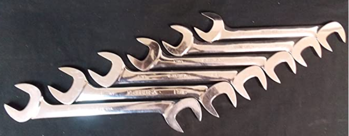
I actually bought a very expensive set of Snap-On Wrenches (my only Snap-On purchase……ever) that had this double open end design and they are worth their weight in gold when you need them. You get 4 different angles per wrench because you get to use both sides, flip around and use both sides again giving you a lot of wiggle room to work a bolt loose in a tight spot where sockets don’t fit and there is little to no elbow room…………interestingly enough these wrenches are a “special” design and have CAT stamped on them as a Caterpillar promotional item. If I remember correctly they were close to $200-$300 for 12 wrenches on ebay when I got them.
Rivets are used anywhere that you don’t intend pieces coming apart……..ever. Like on airplanes the entire outside is typically rivets together because you don’t want bolts vibrating loose up in the air and panels ripping off the plane……..haha. Rivets are an interesting way of fastening items together if you ask me. Another great engineering idea that works in very specific cases really well.
May 31, 2020 at 2:43 pm #566916 sided then. I would expect these bolts would be loosened or tightened using a socket wrench possibly with a short extension needing less elbow room
May 31, 2020 at 5:33 pm #56692Oh yeah this is totally a socket wrench scenario. They probably use impact guns on stuff like this (easy on, easy off)
June 5, 2020 at 4:14 pm #56693As far as the fenders are concerned I think they are complete:
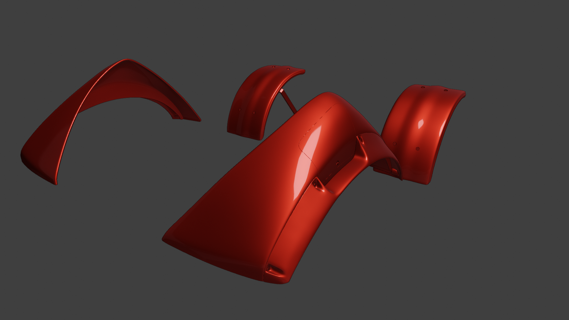
Maybe just some slight adjustments to fit with the Cab, and the front Fenders need to be bolted to the front axle.
As for the Chassis and Stabilizers, Hydraulic lines for the Stabilizers needs to be added, and I think there are more brackets to add to the Chassis. Every time I look at a reference for something else I see another bracket on the chassis.
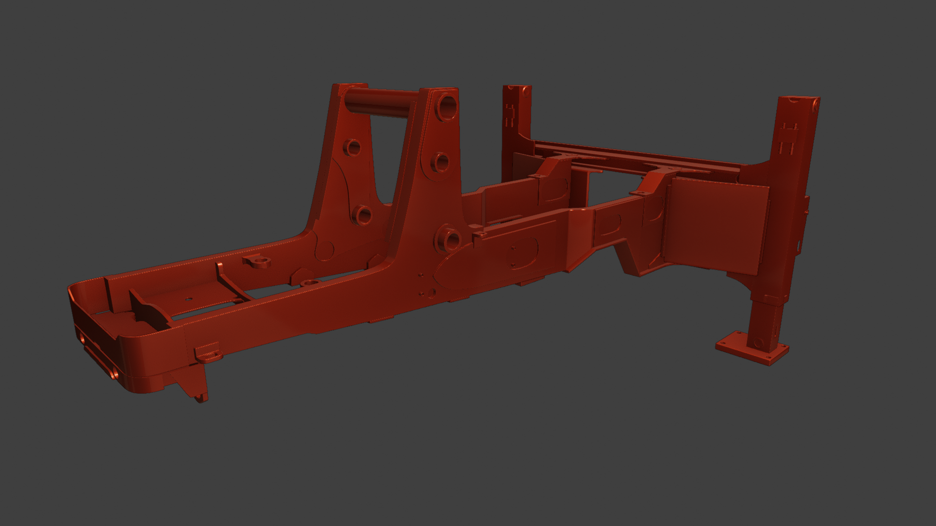
And then there is this, a small extra:
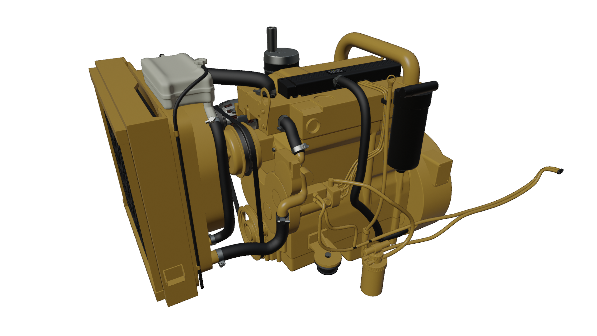
@theluthier Does this count as part of my 50% complete?
June 10, 2020 at 9:32 am #56694Lol just now seeing this. Techinically it’s more like 300+%, but who’s counting??
June 12, 2020 at 8:54 am #56695Just looking over the Fenders and feel they are 99.9% complete. Looking at the detailing on the front fenders as talked about in the live stream,
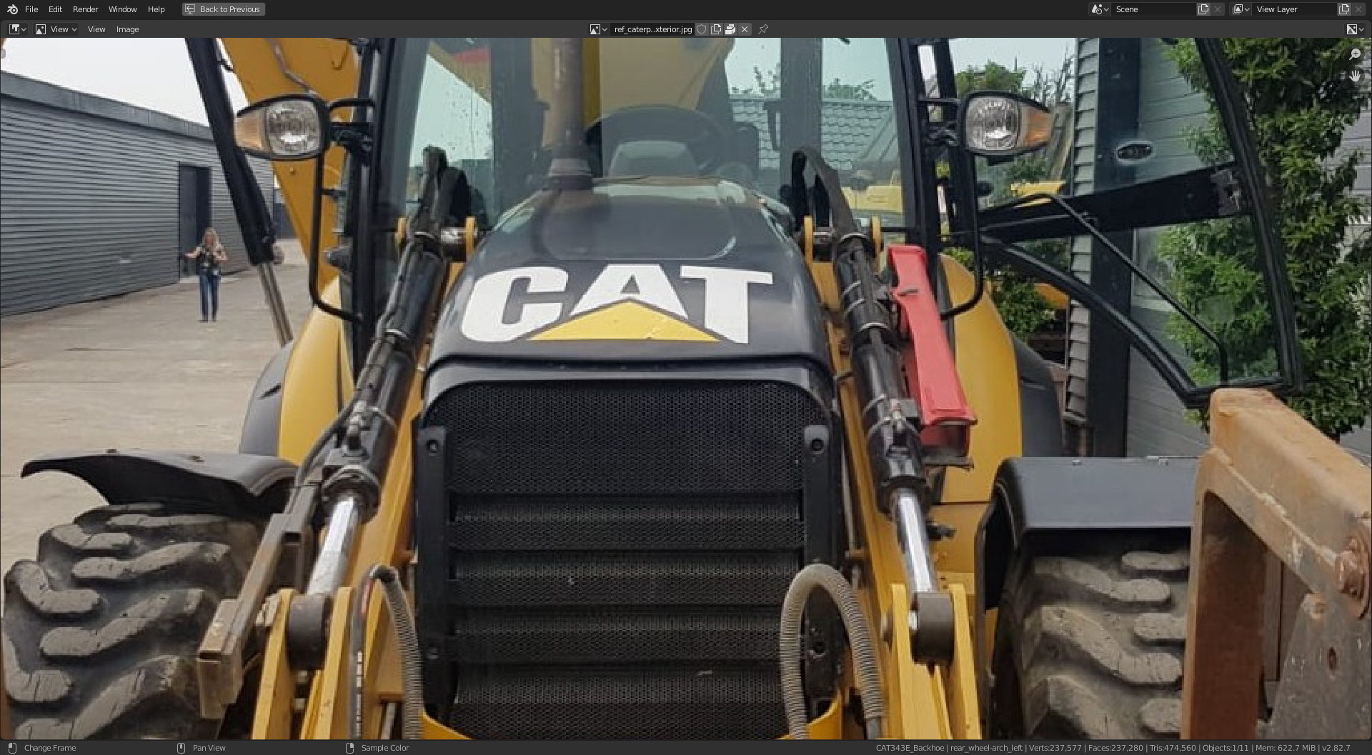
The fender on the right, as we look at this angle, looks like it maybe new, fitted for this photo op. The left looks older and probably the original for this model of 434E. So I will stick with what I see as the original. The new is flat but has the edge detail all round, including across the top. The original has the curvaceous look, but not the detail across the top.
The other point on the rear fenders is the solidify mod,
This is with default, only rim unchecked.
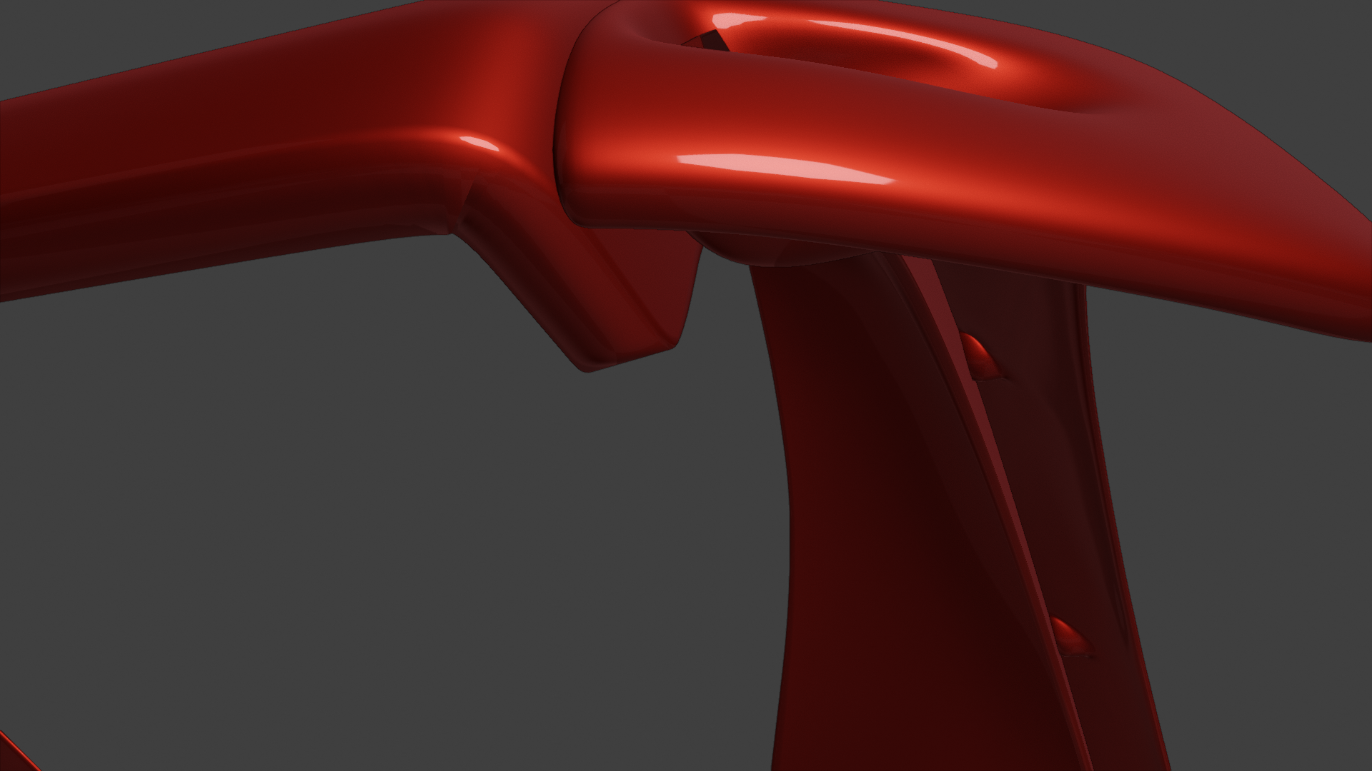
And this with, only rim checked.
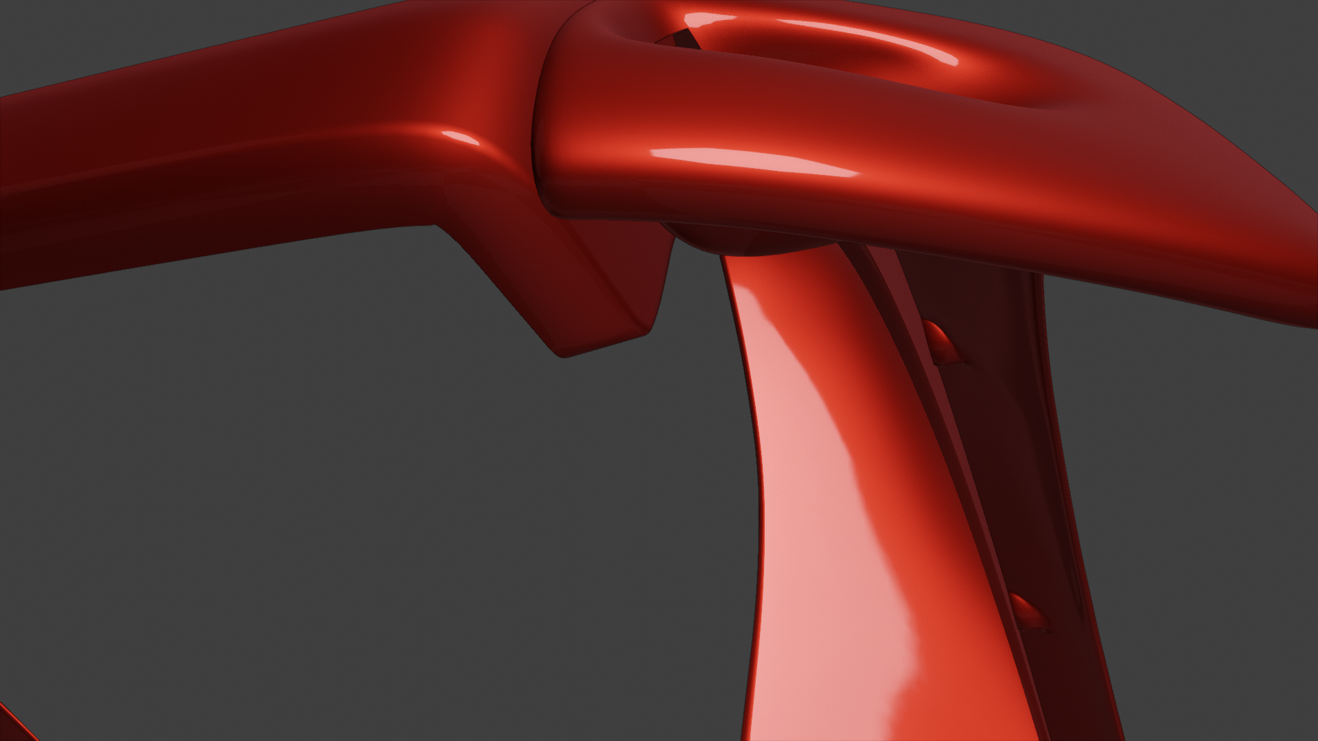
With only rim checked, they corner in particular is much cleaner, the question is do I go for an illusion of thickness or actual thickness??
And one more question for @theluthier , would you rather we upload our file with just our parts but with the naming conventions as previously discussed, or as the master but renamed?? I am finding it easier and faster to have a separate file and link in any other parts for referencing.
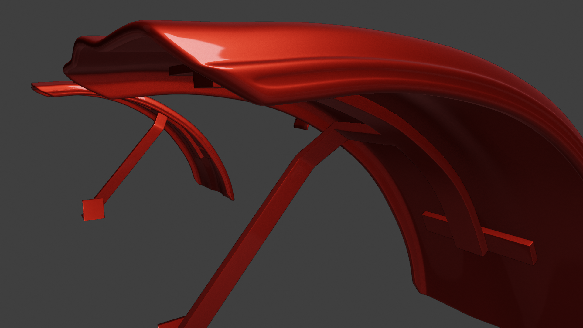
June 12, 2020 at 9:11 am #56696And one showing the front fender detail.
 June 12, 2020 at 9:48 am #56697
Switched the pipe work from my geo based array and curve mod method , to @theluthier (with the help of @dostovel and @spikeyxxx) method as in the live stream. Much cleaner and so simple.
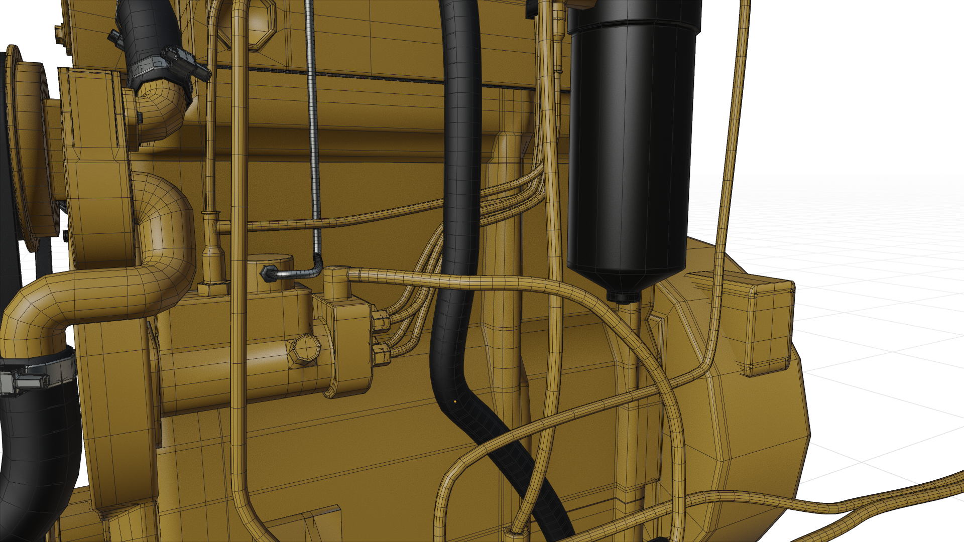 June 12, 2020 at 10:26 am #56698
I really like it @adrian2301. We need to get together to divvy up the remaining engine parts, unless you are lone-starring it.
Also, I have been meaning to ask if there is an end-cap feature to add the crimped fittings onto the end of hoses that use bezier curves? I wonder if it is applicable for some of these lines?
June 12, 2020 at 11:51 am #56699Thanks @blanchsb , I watched the live stream again and had a little smile when I listened to @theluthier ‘s remarks about the engine, and I admit, I watched that bit twice more.
Not too much left on the engine it’s self, the gearbox was next, but that is probably just one big piece, just a matter of the shape.
@jakeblended is on the spaghetti around the swing frame, as @theluthier said , I’m not so sure that part I linked in the stream will be seen, is it worth the effort. I could probably model it in about an hour or so. Jake has a bigger part right behind the swing frame, where all Kent’s and his as well as my 2 lines on the stabilizer all attach, don’t think it’s worth going further than that.
What about your end @blanchsb , do you know how far your going with the lines on your loader arms??
By the way @dostovel I have two fuel lines to go into the fuel tank. Do you want to attach them to the spacer thing I got as far as or do you want me to continue all the way to the tank??? See Below….. Also your parts just need moving forward a little bit on both sides as there intersecting the chassis. I lined the chassis up with the axles and engine enclosure, if you don’t mind.
Do you mean an end cap feature like on the array modifier??
I was thinking the same and did look at the settings , but didn’t find anything.
The best way I found to get an end piece where I want it or the hose to the centre of the fitting is to place the 3D cursor in the centre of that piece and snap the last handle of the curve to the 3D cursor.
Maybe @dostovel will know if that’s possible.
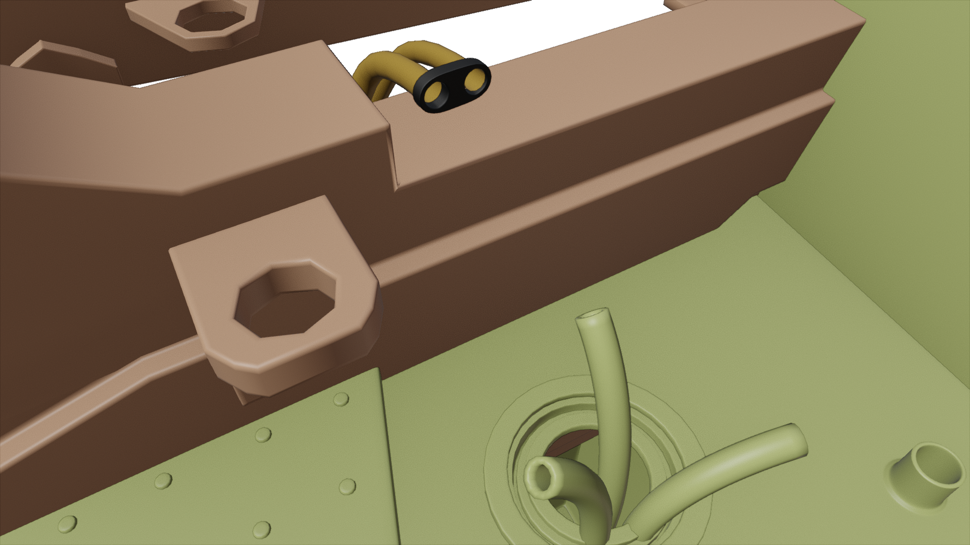 June 12, 2020 at 1:13 pm #56700
No one has mentioned who will be picking up the hydraulic lines that lead to the loader arms from the chassis. I can do some research and work that though. I might as well send the lines all the way over to Parker since they don’t really interact with anyone else. I’ll take a look into that this weekend hopefully.
June 12, 2020 at 2:42 pm #56701@blanchsb I will do these lines 👇as they are actually attached to the chassis. these are the metal ones and then if you take the rubber hoses from there. I haven’t looked yet but I assume this would be the same on the otherside.
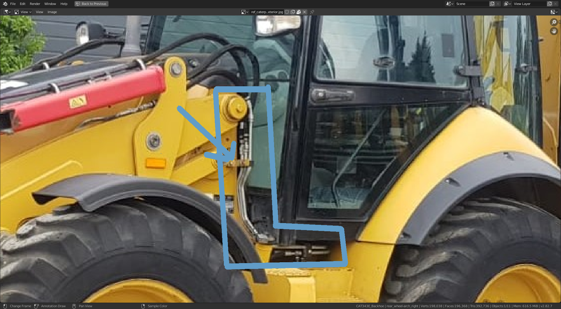
We could have one file for the hydraulics. If I create a file with the chassis, loader arms and bucket linked in, model these lines, and then I will pass the file to you. Then you do your lines, then pass it on to @pfbourassa for him to finish off. That way we can keep them all aligned correctly. What do you think??
June 12, 2020 at 11:41 pm #56702Yeah I like that idea. I’ll work on other fittings and routings until then. Let me know when you have your side ready and I’ll in turn give my stuff to pfbourassa.
June 15, 2020 at 8:40 am #56703Beautifully updated pipe work @adrian2301! Clean and optimal 👌
I watched that bit twice more.
Well deserved! Seeing someone go above and beyond is contagious in a project like this ✊
@jakeblended I’ve finished placing the 8 hydraulic lines from the swing frame to the digging arm. I can throw the file your way whenever you need it. It will probably be best to cut the lines off cleanly with fittings where my lines are come out on one side and yours come out the other (clean separation of work). Just lemme know!
-
AuthorPosts


- The topic ‘Backhoe Contribution – adrian2301 – Chassis/Stabilizer/Fenders and the Engine. And the hydraulics for the swing frame.’ is closed to new replies.