
Collin Jensen

Forum Replies Created
-
AuthorPosts
-
Stopped by to see your work. The wand looks great. I would like to see what you come up with using that massive note document!
RELIC – Final Render
I really enjoyed this Relic course. I learned a lot about baking, retopology, and how to apply a lot of the concepts from the CORE courses I have taken so far! Things like Checker Deselect, Select Similar, Subdivision Modelling, and a little bit of texturing. Spending some time using Blender’s texturing solutions really makes you appreciate using a dedicated software like InstaMAT or Substance Painter. Where to even begin to describe this journey?
Mesh Making
I followed the High Poly > “Mid Poly” > Bake > Low Poly workflow to the letter and found this to be the missing link I had in my baking workflow. I was jumping from High Poly straight to Low Poly (game ready) and was getting the strange shading artifacts that Chunk mentioned. I never knew how to get those to go away, now I do. The High Poly mesh reports 1.32 million triangles, the Mid Poly is 16,700, and the Low Poly is 13,530. I may have gone a little too far reducing the poly count because some of the curves in the “chalice” piece have visible planes in the final render. Thankfully going back and correcting it would be a breeze because we can duplicate the mid poly and retopo from there.
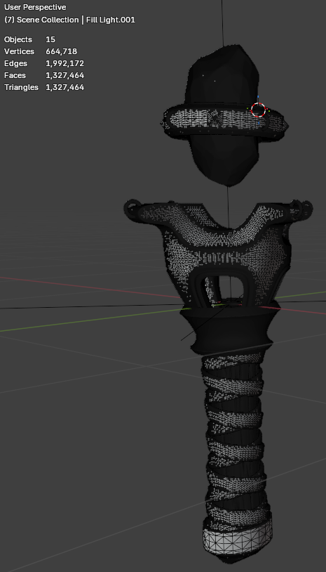
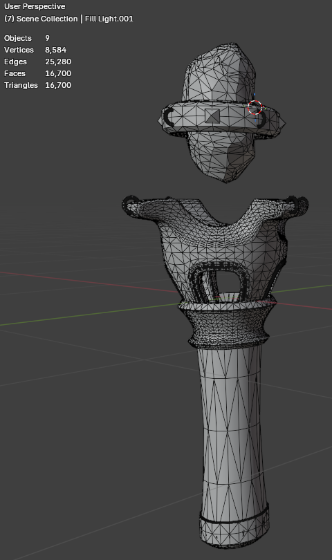
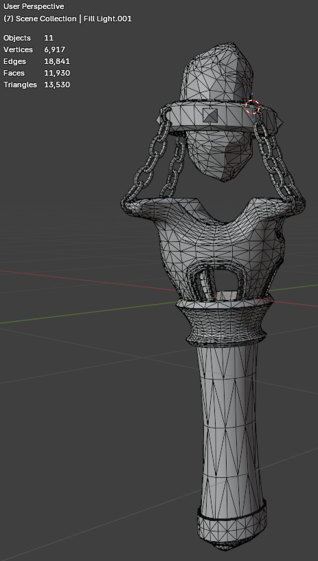
The key takeaway I have from this portion is that the process of retopology is not as hard as people make it out to be. In fact, I find that even the Gem retopo was fairly painless. It’s a perfect opportunity to pull up a YouTube video on another monitor and push vertices around. For a video game asset, this retopology is critical to meet rendering targets smoothly, even with powerful solutions like Unreal Engine 5’s Nanite, why make the GPU do all the work when this process is so easy to do? I suppose it comes down to time.
Texturing in InstaMAT
I was hesitant to install InstaMAT, because I didn’t want to rely upon another subscription-based software. I’ve already abandoned the Adobe suite across the board for this reason. At any rate, the texturing process was incredibly simple because of InstaMAT, and sometimes the dollars spent to save time are worth it (obviously there were 0 dollars spent for this tutorial because of the Pioneer license).
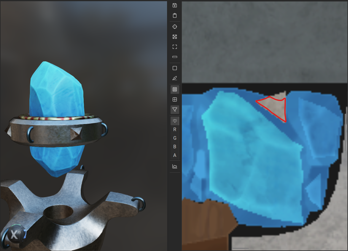
I did have a strange issue where the Bake in InstaMAT caused parts of the Gem to show up on the spikes, which caused masking using the Material ID to not function properly.
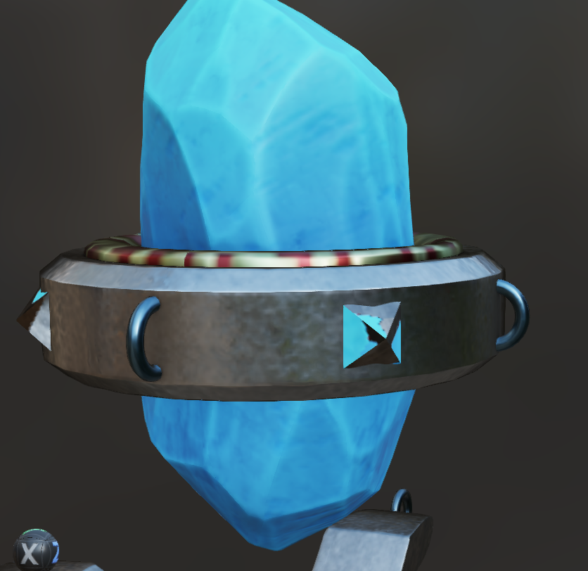
I decided to create another mask from Blender to mask off the spikes like we did for the leather straps. This was accomplished the same way, using the emission of the object to bake a black and white mask. Then, in InstaMAT, I used it in a Mesh Project Mask in Subtraction mode on the Gem to remove the gemstone bits from the spike. I then used the Mesh Project Mask with the Default mode to mask off the spikes and apply the metallic surface to it. Putting the Spike texture above the Gem means that the mask on the gem should be largely irrelevant, as far as I understand the layers. You will notice that it still isn’t perfect, and I’m not exactly sure why. The color map even looks like it should be correct. This probably has to do with the bleed settings on the color map, since the blue is clearly bleeding over the triangle of the spike when it shouldn’t and is causing problems.
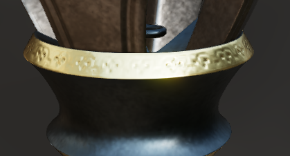
I also decided on a more frosty look than the tutorial, so I have a gray metal instead of the gold Chunk used and the blue crystal. Aside from that, I opted to add an engraving to the top of the collar on the gold. I did this in the same way Chunk made the vertical lines along the collar.
Rendering
I chose to make my background orange to make it a complimentary color to the blues in the wand. I added a three-point lighting setup from the lighting course earlier to provide a nicer lighting setup. I used lights that fall on the cooler side to further sell the frosty vibe.

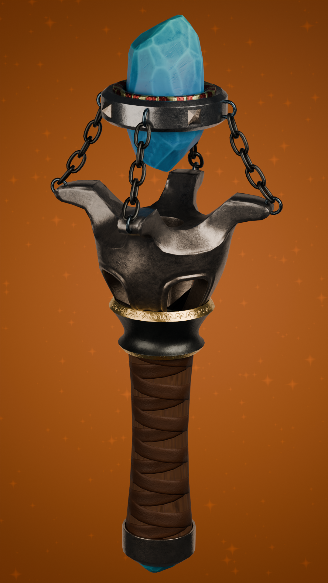
Now it’s time to move on and create something of my own and use this course for reference. I am really satisfied with the result here and hope to apply these concepts to future models.
RELIC – Game Asset Creation Homework 2
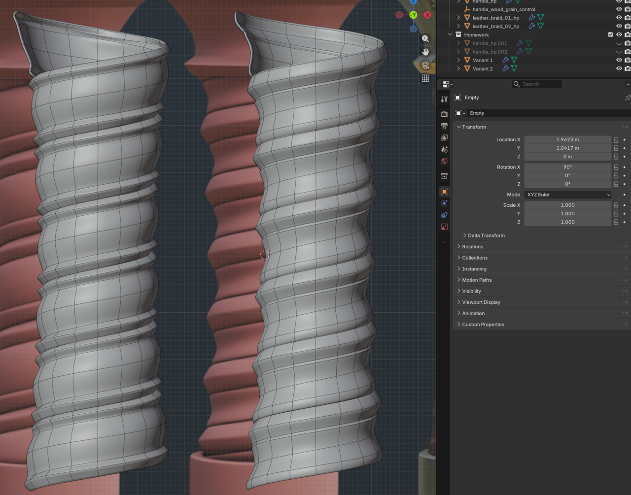
The second homework task was to recreate the other two handles included in the source material. Using the same Screw Modifier + Shrinkwrap Modifier + Solidify Modifier workflow, I was able to come up with these results. Changing the basic shape of the handle is fairly straightforward, because we can control the shape using Alt+S to scale along the normals. To make the sharper edges after the Subdivision Modifier, I used Edge Creases, although I suspect that the really sharp edges in the reference were created by having separate objects. I opted to use a single screw object, which means my shapes are a little bit different when it comes to shading.
RELIC – Game Asset Creation Homework 1
While doing the relic course, Chunk asked that we post a different version of the handle here. The basic rundown of the first video is that this handle is created by using a curve, then converting the curve to a mesh to get the basic shape. Then the mesh is “sculpted” using a few displacement modifiers to give it texture that will later be baked onto a low poly model.
I found that using a tiny Voronoi Crackle texture for the distortion resulted in these meandering lines. This could either be the grout lines from a cobblestone version of the handle, or the little bug trails left behind on trees that are lived in by bugs.
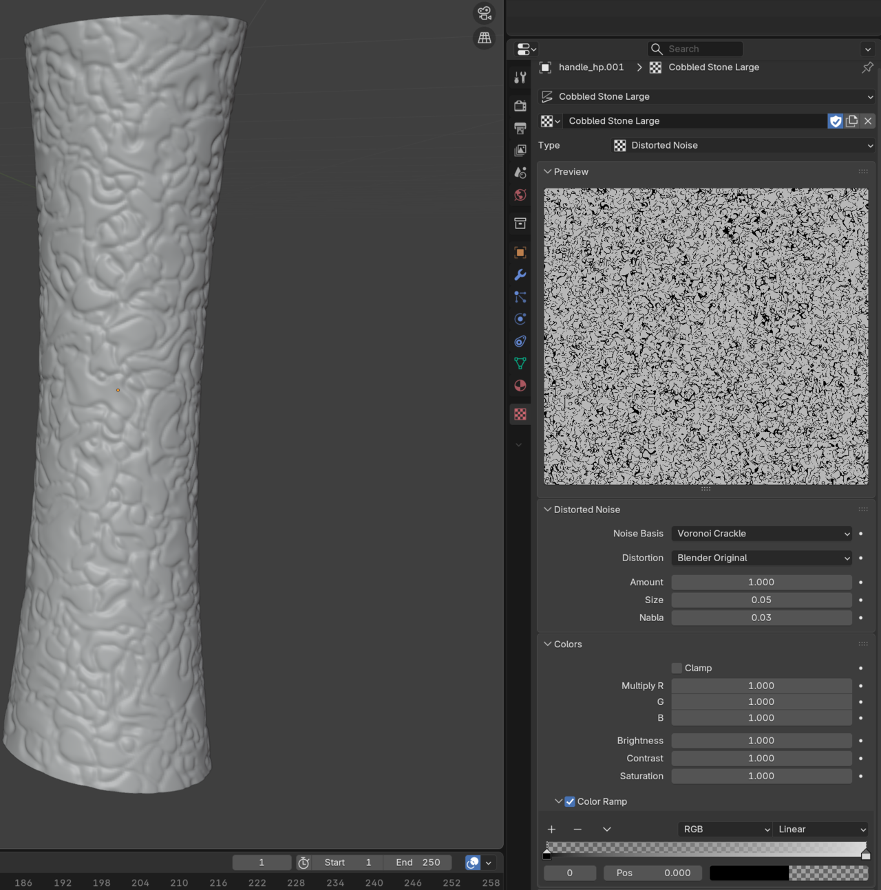
After that, to make it a little more interesting, I added a perlin noise distortion to give it a more stone look. I thought stone might be an interesting handle for a magic item, how often has glued-together stone been used as a handle? Rarely, for a lot of practical reasons like tensile strength and weight, I am sure.
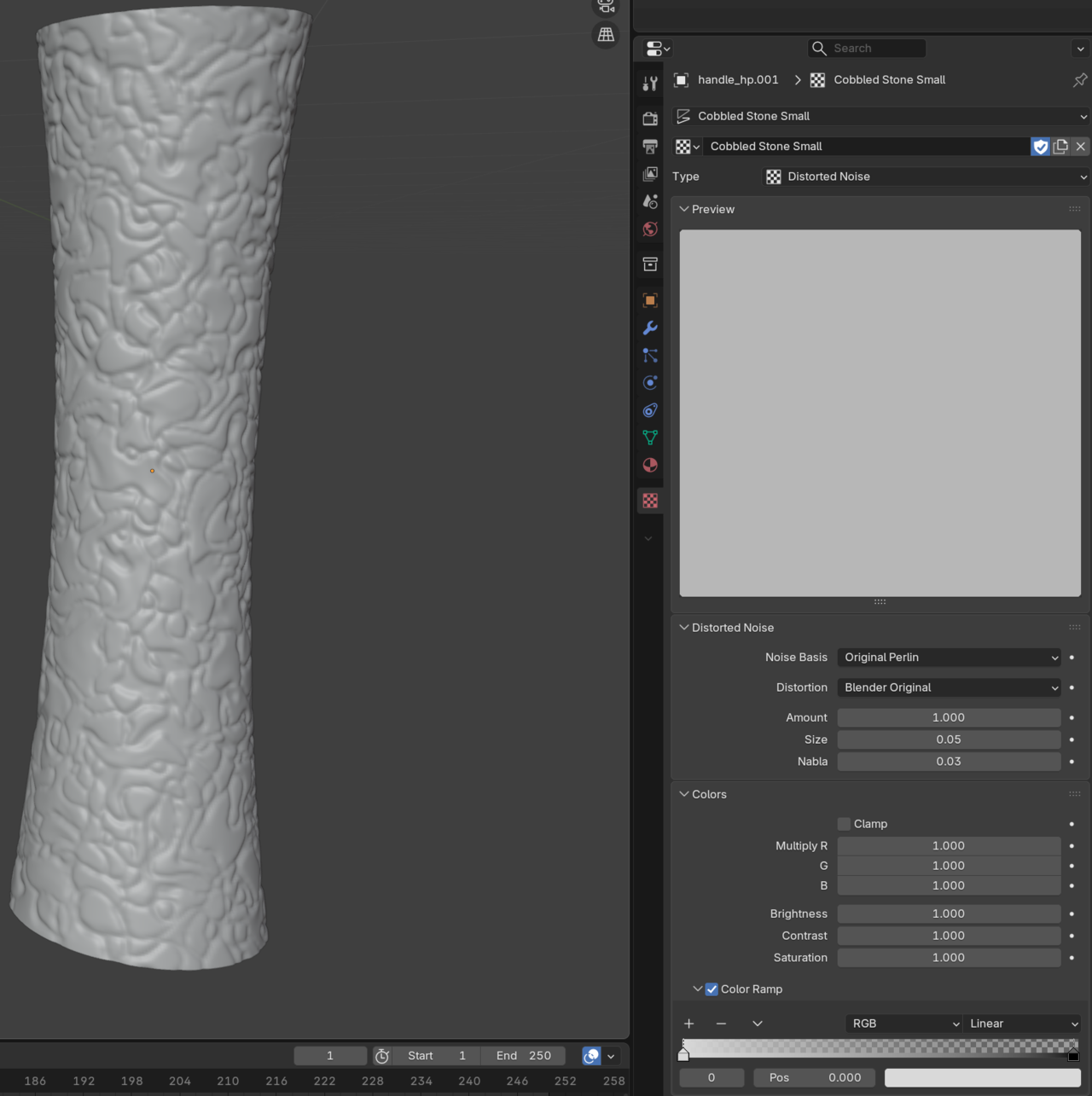
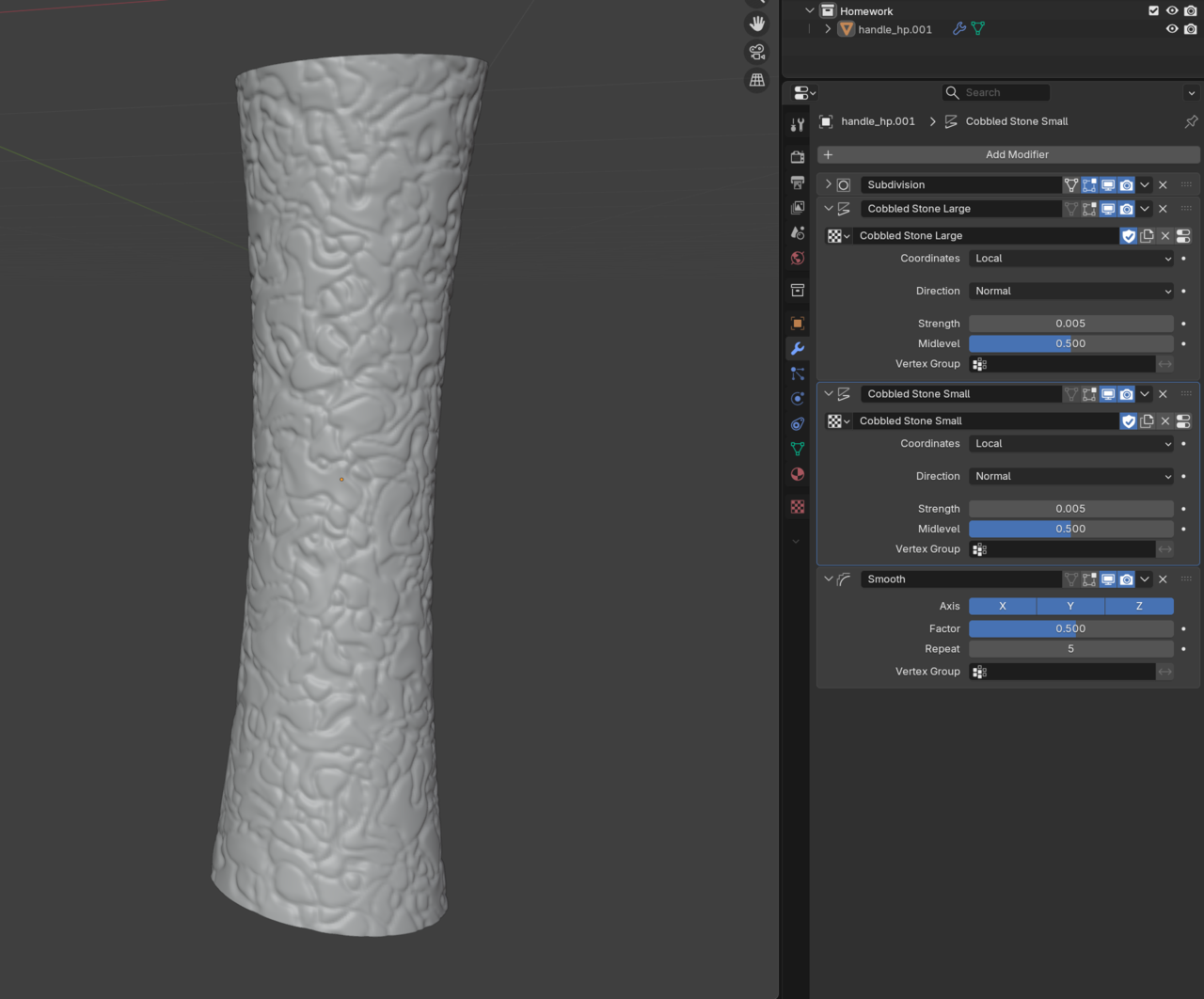
With these two distortions combined, the texture starts to look a little bit more like a bunch of misshapen stones glued together. Here is the final modifier stack.
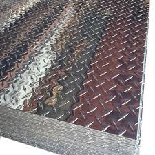
That’s a good idea, Martin! I was torn between these two reference images, either making the sheet incredibly smooth or incredibly rough. I probably should have given it a little bit of noise and roughness to make the metal a less perfect mirror.
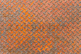
Procedural Rusted Diamond Plate
During the Texturing course, they request rusted metal. I wanted to make this metal into Diamond Plate, which was done easily with the Brick Node.
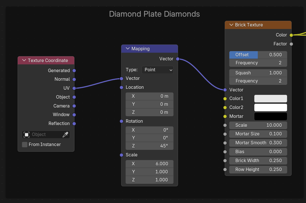
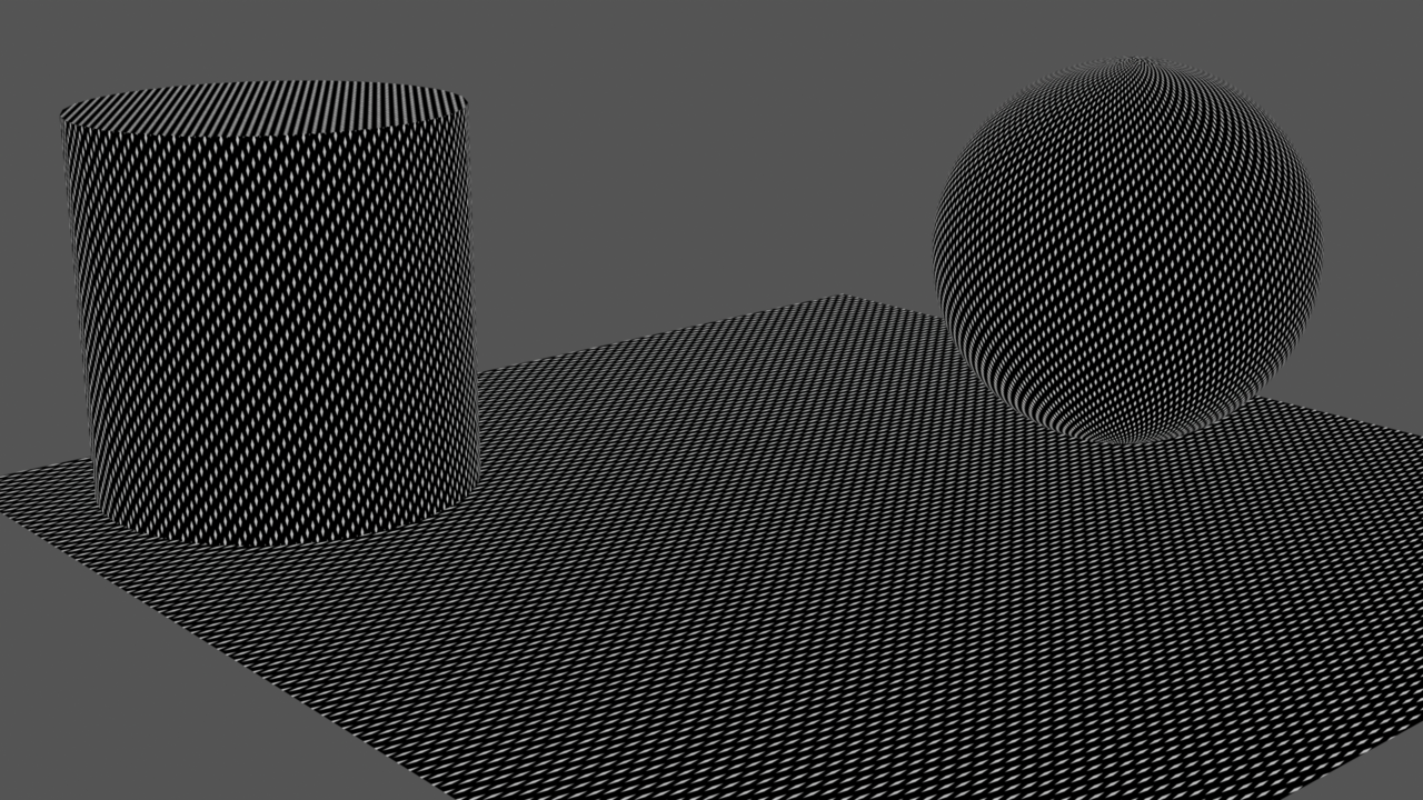
The diamonds use the custom UVs because I had to do a UV unwrap on the cylinder to make it look right. The result is a black and white mask that I used to create the normal map and make the tops of the diamonds shiny even in the rusted spots due to wear. This is useful later, but for now, I needed to make the rust. This is the result so far.
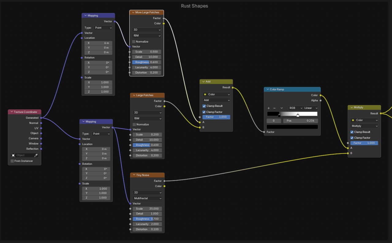
Rust Shapes
The next step was to create some rust splotches using Noise textures. I started with a single noise texture, but that wasn’t enough and I wound up using a few of them. I wanted the edges of the rust to be rough and chaotic, so I mixed a small texture in with a larger texture to give it that texture. The result here was few large splotches, but they were too sparse, so I combined a third noise texture with it to finally land on the shapes of the rust.
Rust Color
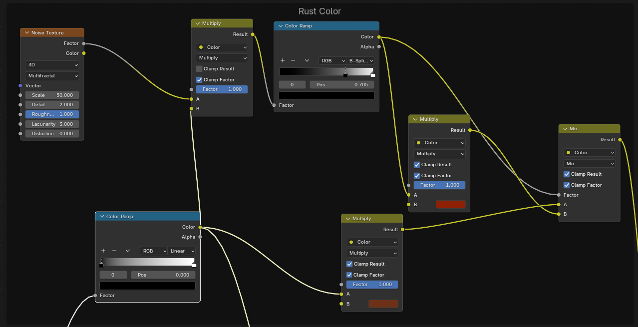
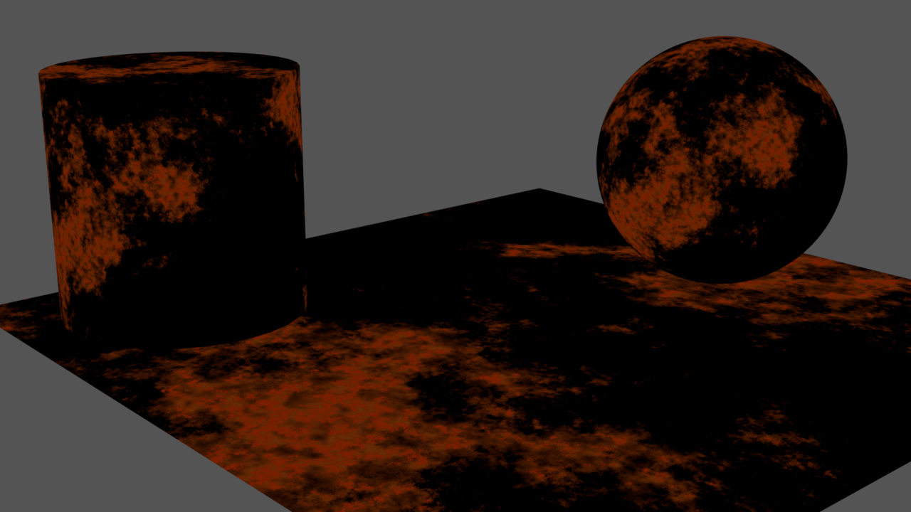
With the rust shapes out of the way, I needed to color it. I settled on a dark, reddish brown for most of the rust. After messing around with it a bit, I wanted some smaller pieces of it to be a little more red. I used yet another noise texture to add in that rust red color randomly within the brown. I had to experiment here with the blend modes a lot and found that multiply resulted in the colors I wanted. I can adjust which parts of the rust are brown or red using the color ramps and the color ramp for the red is used as the factor for the final mix node that brings it all together.
This is the resulting rust splotches so far:
Metal Color
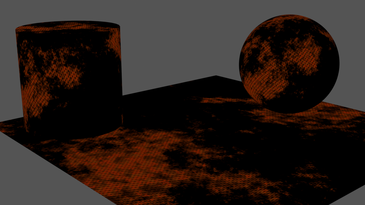
The metal coloration was simple enough to add, but at this point the rust needs to be adjusted to let the gray of the metal through wherever the diamond plates are. This was important to me as both a challenge to learn from and how the metal needed to look for me to be satisfied. The effect is fairly easy, we need to cut a hole in the rust coloring using the Diamond Plate mask from before. I did so here.
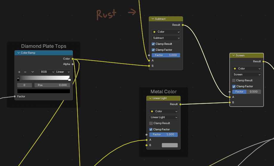
This is the small change to the rust map this made. Notice how there are now black diamonds in the Rust.
Roughness and Metallic Maps
For the desired effect, the rusty parts need to be rough while the diamonds and rust-free metal are shiny. That means I needed to do the same thing with the roughness map as I did with the Metal Color above to make the diamonds shiny.
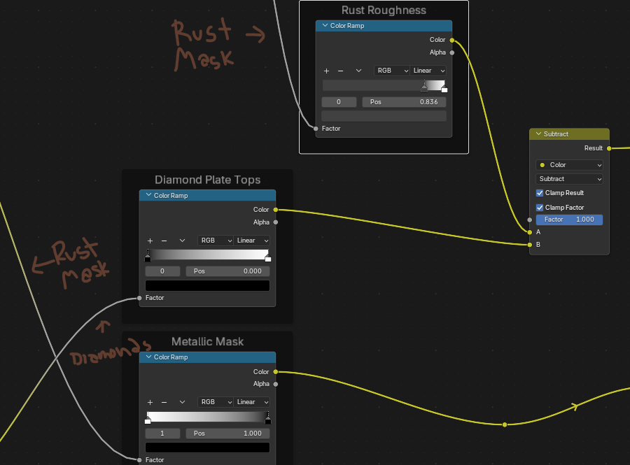
The result is a roughness map that looks like this, where the shiniest parts (black) are the diamonds, the metal is a mid-tone, and the rust is the most rough (white).
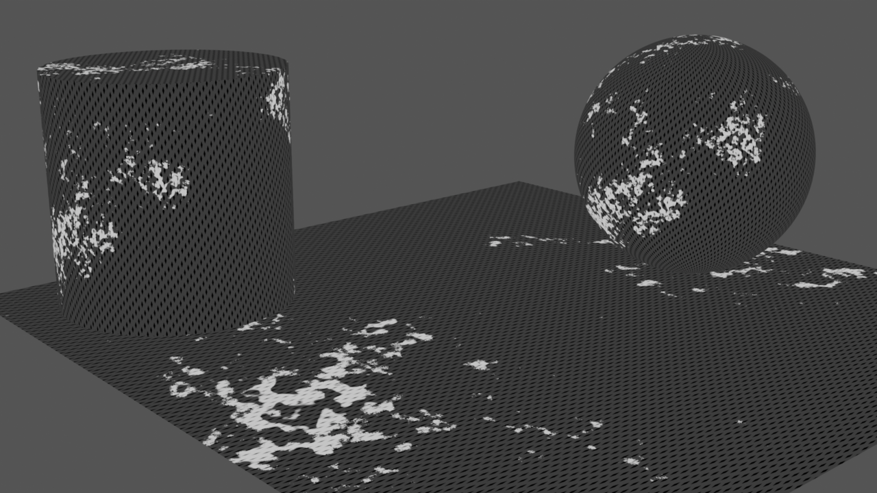
Final Render
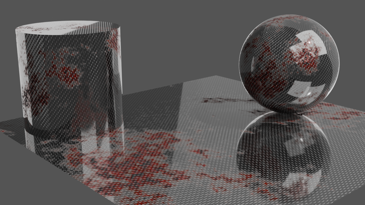
Depending on the needs of a project, it might make more sense to have the diamonds actually displaced or model them with something like an array modifier. I wanted to have a fully procedural solution to this problem, though so I’m happy with the results. For a real-time application like a video game (which will eventually be my focus) this approach using less geometry is easier to render. For me, the hardest part was getting a decent lighting solution for this setup. Eventually I settled on this one, which uses a separate rim light for both the sphere and the cylinder and a single fill light for both. There are two key lights to light the area, resulting in them being visible on the sphere due to their reflective nature.
Lighting Submission
I worked through the Lighting course today. The course was good, I learned a lot about properly lighting scenes, especially those with a focus on a single object. When the instructor walked through the lighting for the scene in the final project, I got a bit confused. Adding all of the additional lighting to the scene to make rim lights and fill lights that ignore objects resulted in a look that felt overexposed to me. Like most things in an artistic endeavor, though, it’s probably something that’s closer to personal preference rather than a hard science?
Here Comes the Sun
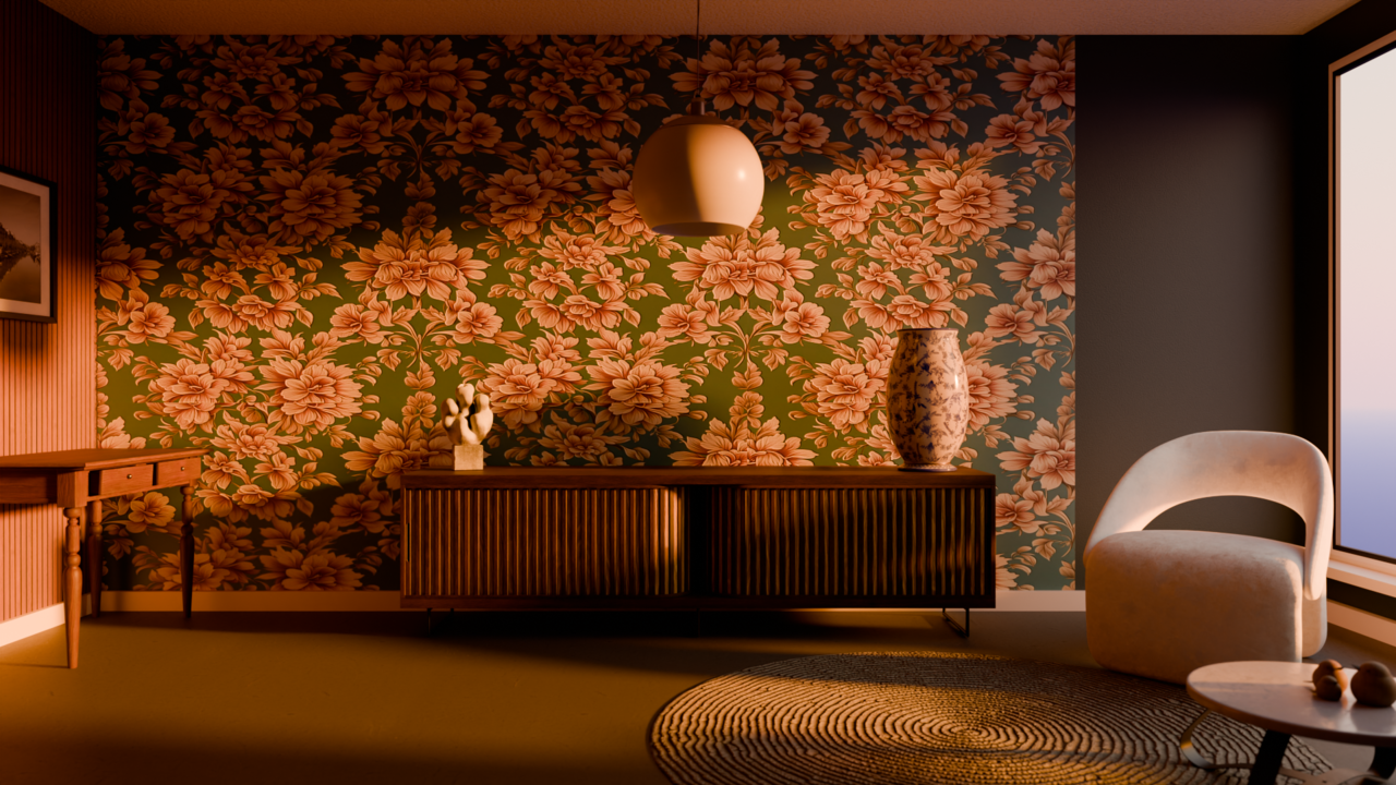
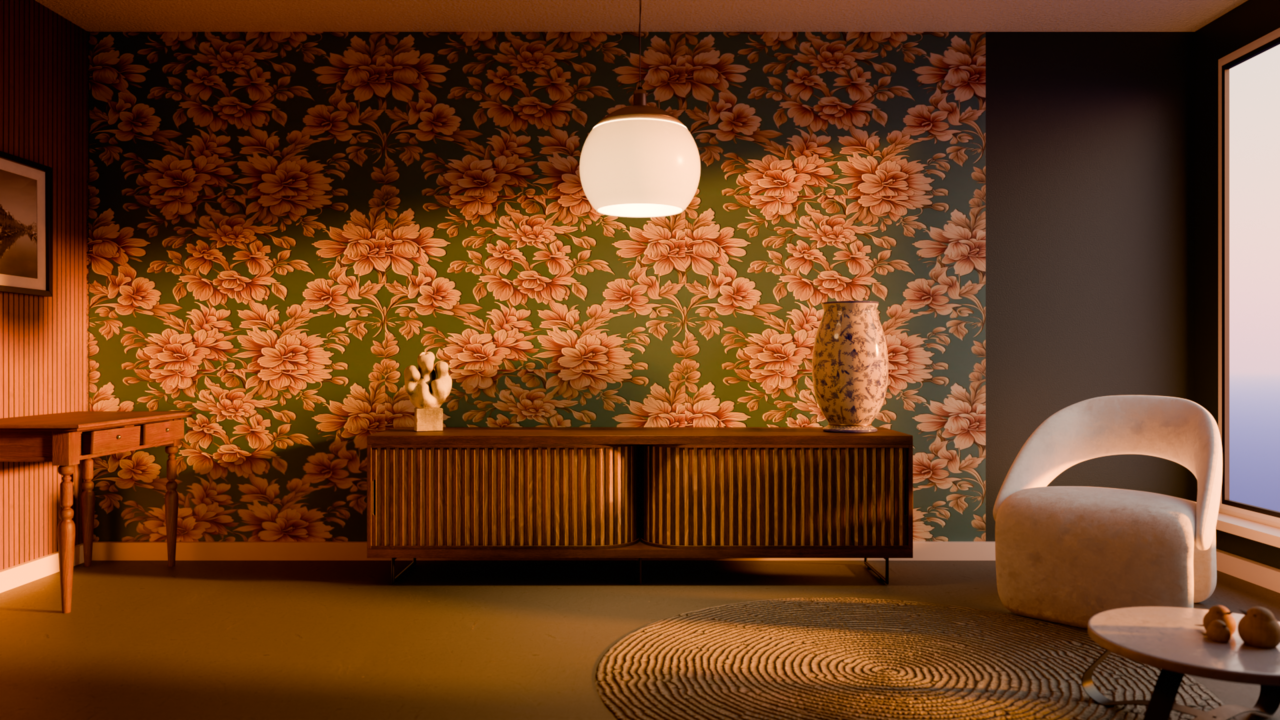
I wanted to light this room so that it is warm an inviting, so I used a Sky Texture to make the sun set a rich, orange color. This is what the scene looks like with only the sun filtering through the window, which I like a lot.
Adding in More Lights
I think the warm theme I wanted is nearly achieved at this point. The long, harsh shadows cast by the chair and table near the window made the scene less inviting, so I made the ceiling light a warm color to push those shadows into a more inviting tone. The rest of the fill and rim lights for things like the statue, vase, cabinet, and sparrows were variations in power and value from the original light. All of that means the final scene is lit with a monochromatic orange lighting scheme, which I think turned out nice. It achieves an inviting atmosphere with the warm tones even though I might like the more dramatic lighting from the window-only lighting. The rim lighting on the left of the cabinet helps to show the leg of the cabinet better and the details of the front of the cabinet is better defined with this new lighting setup, using two fill lights and the center ceiling light to ensure the front of the cabinet is lit enough to see. I wanted to maintain the dark shadows from the cabinet to sell the fact that the sun is setting.
Final Render
Things started to click into place for me as I lit this scene. The really dark shadows from the sun obscured the scene and made it difficult to see the features on the center cabinet. The lights added help define the scene, and while I still think the original lighting setup for the scene in the tutorial is a bit harsh, I understand the concepts and look forward to applying them in the future.
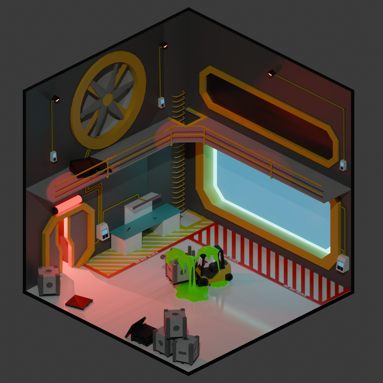
Low Poly Room: Sci-Fi Hangar
I have finished putting together my Low Poly room for the submission and the final project of the Mesh Modeling Course. I wanted to make a Sci-Fi-themed room after the tutorial for the Sci-Fi Box, I also wanted to capture a feeling that something has gone wrong in the room. That’s how I landed upon this Sci-Fi Hangar that is in red alert after some poor forklift operator had a mishap with whatever strange green ooze was in their crate!
Elements of the Snowman Tutorial
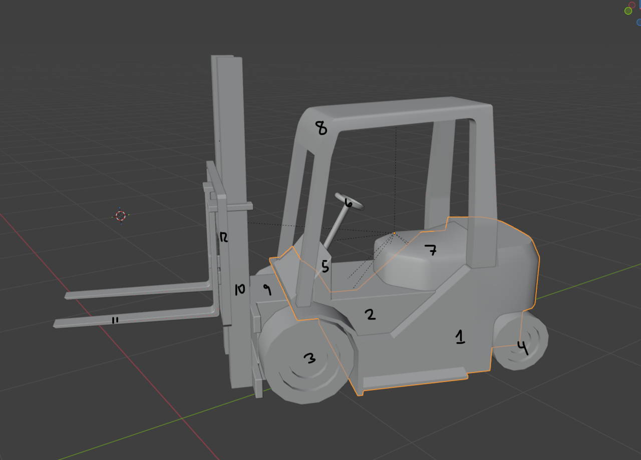
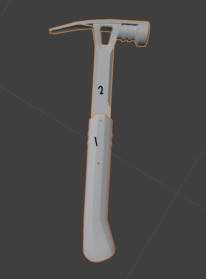
I wanted to ensure I used pieces from as many of the projects leading up to this one as I could. That means many of the objects in this scene are collections of simpler objects. The control panels on the walls, the hammer, and the forklift are each a collection of simpler, separated parts connected together using the Parenting technique used in the snowman tutorial.
Sci Fi Crate Tutorial Elements
The Sci-Fi crate tutorial introduced the Mirror modifier and bevels to create interesting Sci-Fi elements. I created a new Sci-Fi crate for this project using the same mirror modifier setup and a pallet that has some of the panel lines introduced in the guided crate.
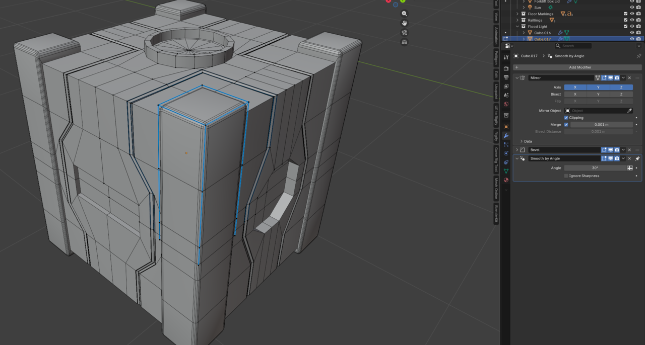
The Mirror modifier has always been my favorite modifier, so it is used all over this project. I used it to create the rungs for the ladder, the light fixtures, all 12 of the forklift parts, and the palette.
More Modifiers!
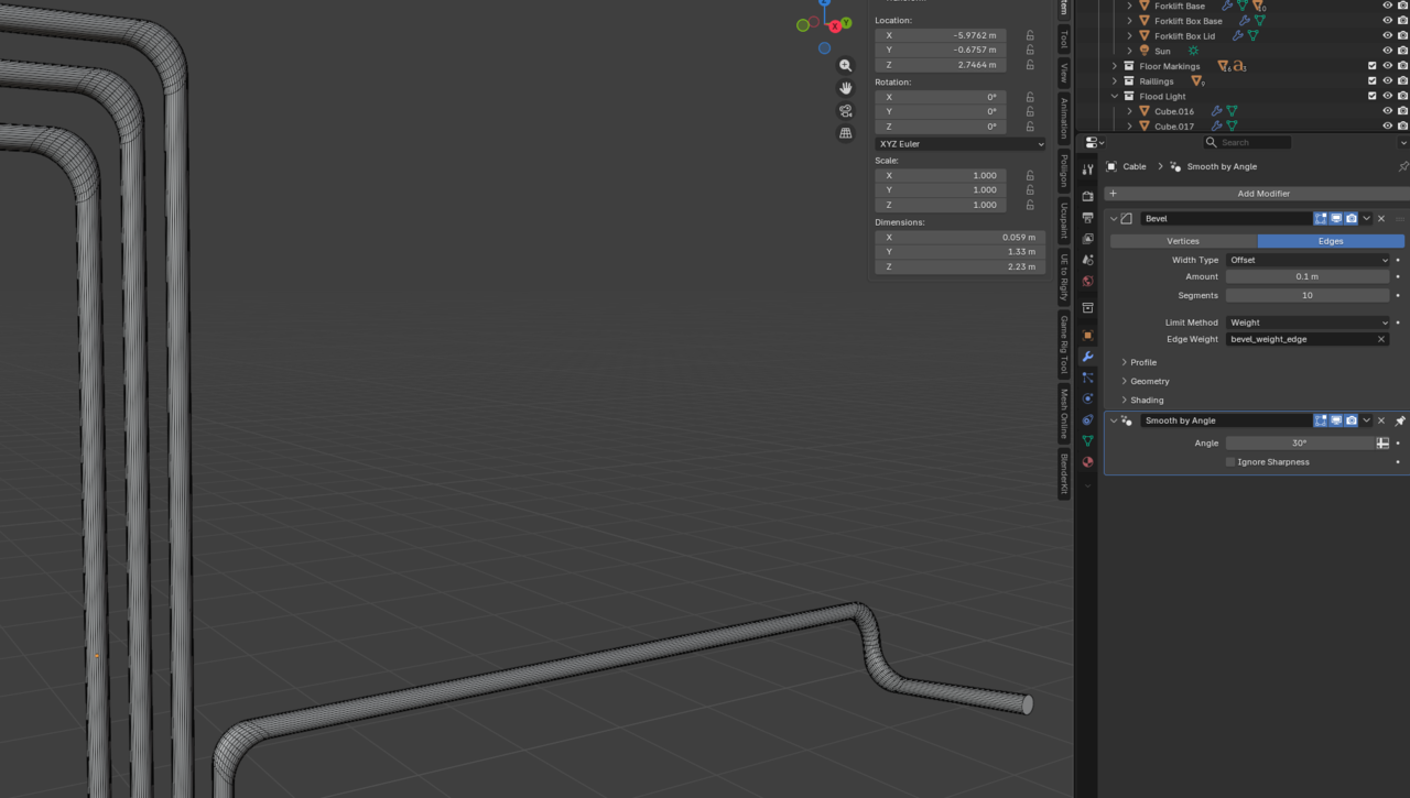
The bends in the yellow cabling on the wall use the Bevel modifier to get a curve. A consequence of this method is that the corners are a little bit distorted. I tried a few different methods for this, but I didn’t mind the slight distortion on the corners and it was the simplest to manipulate. This was useful in maintaining a uniform appearance while making new corners easy to create since I had to lay out 10 cables with 22 bends in total.
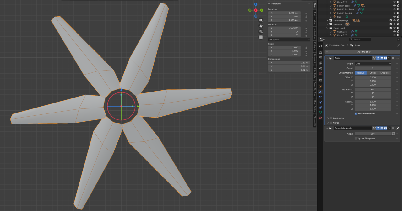
The Array modifier was used in some specific applications for this project as well. I needed to lay out the diagonal hazard markings on the floor evenly, which is where the Array modifier excels. I also used it to evenly distribute the blades on the big fan rotating one blade around the center of the fan to create all of the blades.
Elements of the Coffee Mug and CG Cookie Logo Tutorials
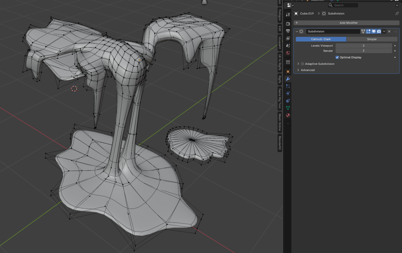
I added the slime coming out of the box because I wanted to try modelling a more organic form using the subdivision modifier. I was careful to use quads as in the CG Cookie Logo tutorial so that the form looked like dripping slime. The slime loses some of its visual appeal up close, but I learned after creating the hammer and pliers that a lot of the small details are lost when you zoom out to the camera perspective that captures the entire room.
Key Learnings
The first course in my CG Cookie journey has been a ton of fun, and I’ve completed more 3D models in the last 30 days than I have in the last 8 years messing around with Blender. I have been constantly reminding myself that “perfect is the enemy of finished”. There are some imperfections in each model I have created, but the overall result of each project is something I am proud of making and no project will ever be flawless. I learned how to better use Bevel Modifiers, which I had never used in my modelling before, and was blown away with their application in the Hard Drive Tutorial. I learned more about the Subdivision Modifier and how to properly lay out quads to support important geometry when the modifier is on. I also surprised myself with the sheer volume of objects I can make using the information provided in the course. This project also taught me the importance of keeping the final render in mind when modelling objects. I put far too much time and details into the hammer and pliers for how large they ended up being in the final render. The minute details were lost in the final render, which is a bit of a shame, but a valuable lesson learned. Mirror modifiers, array modifiers, and linked duplicates make it easy to manipulate multiple objects at once, reducing the work required by half or more!
I look forward to some more amazing 3D modelling work in 2026 and sharing it here with you. Happy New Year everyone!
Cool box! Its got some nice Sci-Fi greebles.
@thehomme I look forward to the Luminor course and the room! I agree, it blew my mind at how simple the Hard Drive wound up being to make when the Bevel modifier was used. It looks just as good as my subdivided mesh, with fewer triangles. A win-win!
Coffee Cups
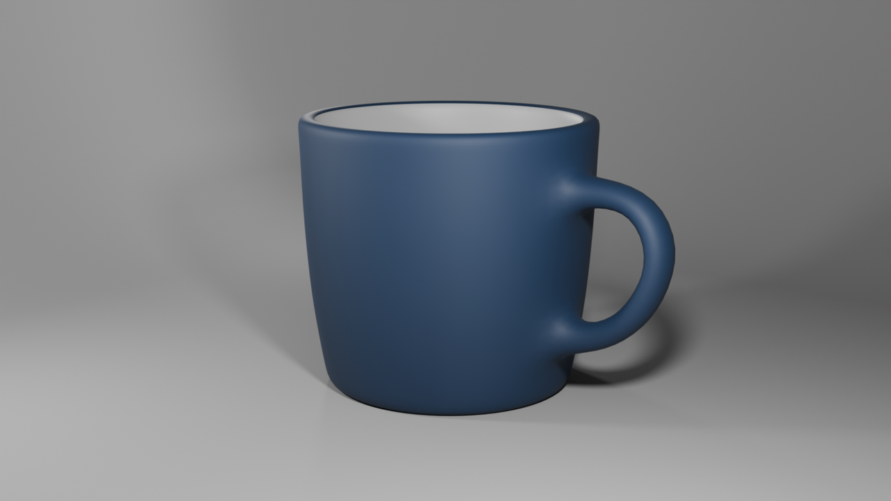
I have started on the subdivision portion of my journey with the first tutorial being the coffee cup. I found it a bit strange that the first video explains the benefits of using the Bevel modifier to sharpen the edges of a subdivision surface and then this video doesn’t use them. I understand that the loop cuts are probably more beginner-friendly. So, here’s my coffee cup:
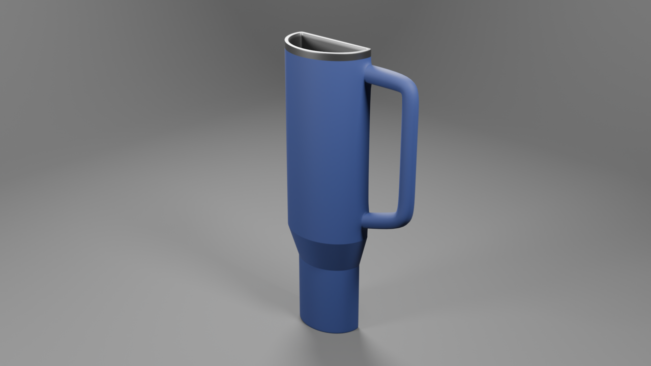
The New 20 oz Stanley Cup
My new mug to practice the lesson was a cup I keep seeing everywhere, the Stanley cup. This design takes the 40 oz tumbler and slims it down. Same height, same width, but half the depth.
For the technical usage, I tried out using the bevel modifier with weights where it made sense, so along the rims of the drinking end of the cup, around the parts where the handle connects, and the very bottom of the cup. To make the sloped part sharp, I just used edge creases set to 1. It might have been more visually correct if I had used a bevel or supporting edge loops instead, since I doubt the real life Stanley cup is actually that sharp. I also think the handle is too long, which means the proportions between the wider top part and the thinner bottom part aren’t quite right. If this were a serious project, I would fix those problems, but it’s more about the subdivisions than proportions.
Do you think Stanley will hire me?
Hard Drive Part 2
I have just finished the video and the primary takeaway I have (which matches what @thehomme pointed out) is that I shouldn’t have forgotten about weighted bevels! The bevel modifier is a new one for my toolkit, so I really only used it for the tiny bevels along the edges. The video uses a shader bevel instead, which isn’t a problem. I’m hesitant to use the shader bevel because it seems like it could get complicated when you start to bake normals. By that I mean, when we do a high-poly to low-poly bake, I imagine the shader bevel would have to bevel certain parts of the normal differently in a way similar to weighted beveling for the bevel modifier, rather than applying a uniform bevel across the hole piece. I also could be very wrong, since I haven’t done a whole lot of normal baking.
The freedom given by the bevel modifier and other non-destructive workflows like it, is that we can freely modify them at any point in the future. The video does this, and at one point I had to manually modify a bevel I manually created in this project. Ew!
There are some details of the hard drive I got wrong simply because I stopped watching it when he said “You should go try this yourself first.” Things like the real world scale of the hard drive, the fact that the bottom of the main case is beveled, and the fact that there are 6 total tiny rubber feet on the bottom, while mine only has 4. Also, I didn’t realize from the screenshot that the little light bar below the letter sticks out. These are nit-picks akin to the video perfecting that bevel on the front panel to match the case, so I’m not worried about them at all.
So yes, as Martin and Omar have pointed out, the end result of my work works so the ways my methods differ isn’t necessarily incorrect. However, I really like the elegance and simplicity of the method used in the video, primarily because he used weighted bevels to curve things. He also didn’t use a subdivision surface modifier, so his final mesh is likely less dense than mine, and triangle counts do matter in some applications. I’ll have to give the weighted bevels another visit, since I used exactly zero of them in mine!
Thanks for all of your feedback! Since this project was created before I watched the video. I think I’m going to move on the subdivision surface modifier section instead of creating a second project akin to the Hard Drive. I anticipate using bevel modifiers a lot in that part of the course!
I finished the Hard Drive from the Hard Surface Modelling, but I haven’t watched the video on how it was done. Here are my solutions to the problems presented and the final result.
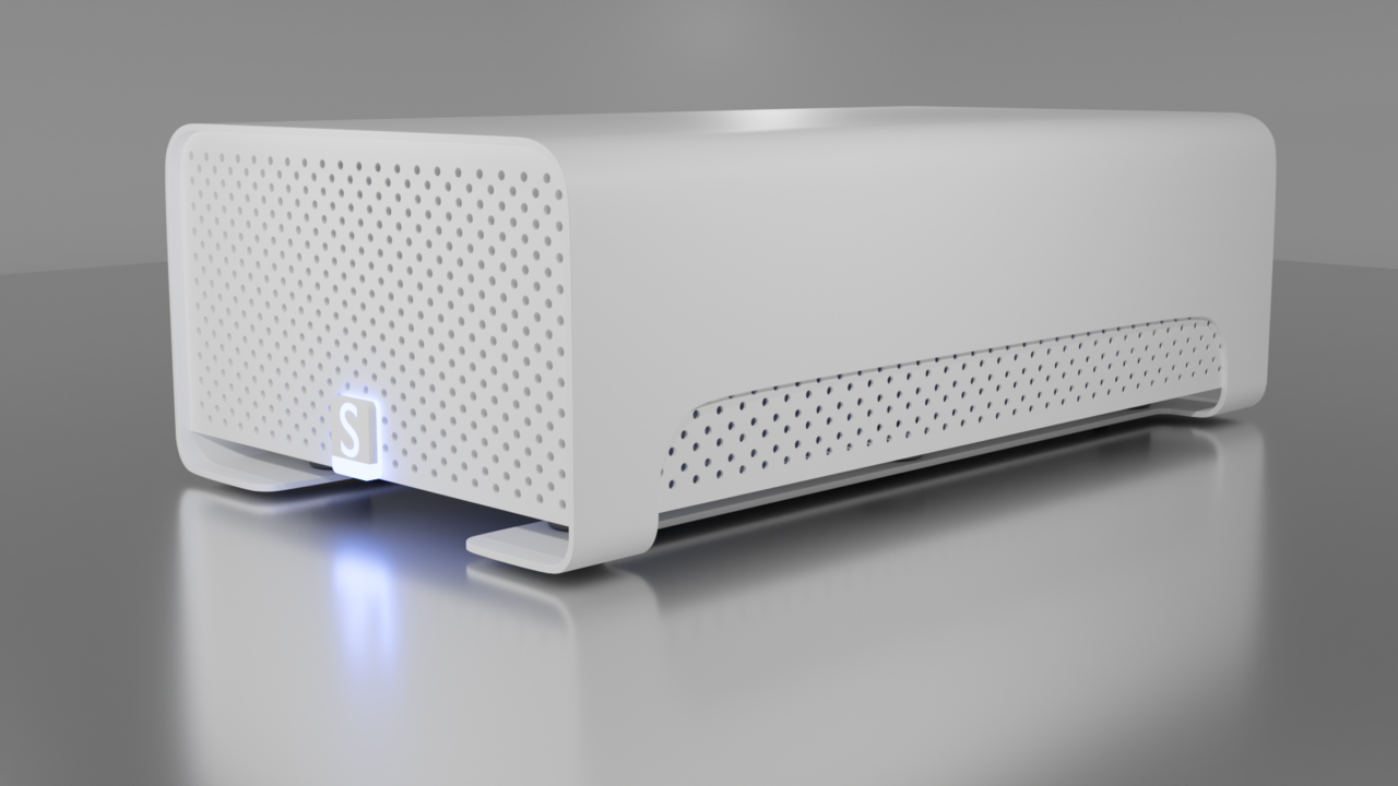
The Shell
First, I started with the curved outer shell, making use of the Solidify modifier to make managing the geometry easy because it is a single plane. This was useful, because when I was preparing my final render, I realized my Hard Drive was too short, so I had to make the shell and front face taller. I created manual bevels for the curves by either Edge Beveling or Vertex beveling. In the past, I have had the “Only quads unless it’s impossible” mantra reinforced a lot. I tried that out here, but like any tools in 3D, sometimes the supporting edges provided for a quad are required:
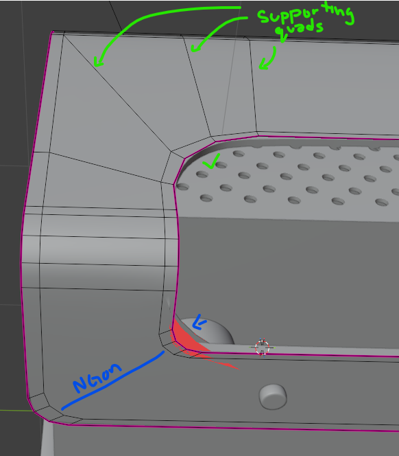
The final result used a lot of non-destructive modifiers, making modifications to the mesh easy, even if changing from edit mode to object mode took a couple of seconds. I recognize that the two loop cuts that go across the top are probably unnecessary, since they’re really only there to support the curve on the side. Would it be worth localizing that geometry for this model by adding a loop cut that runs along the side? Perhaps this is answered in the course video I plan on watching after this post.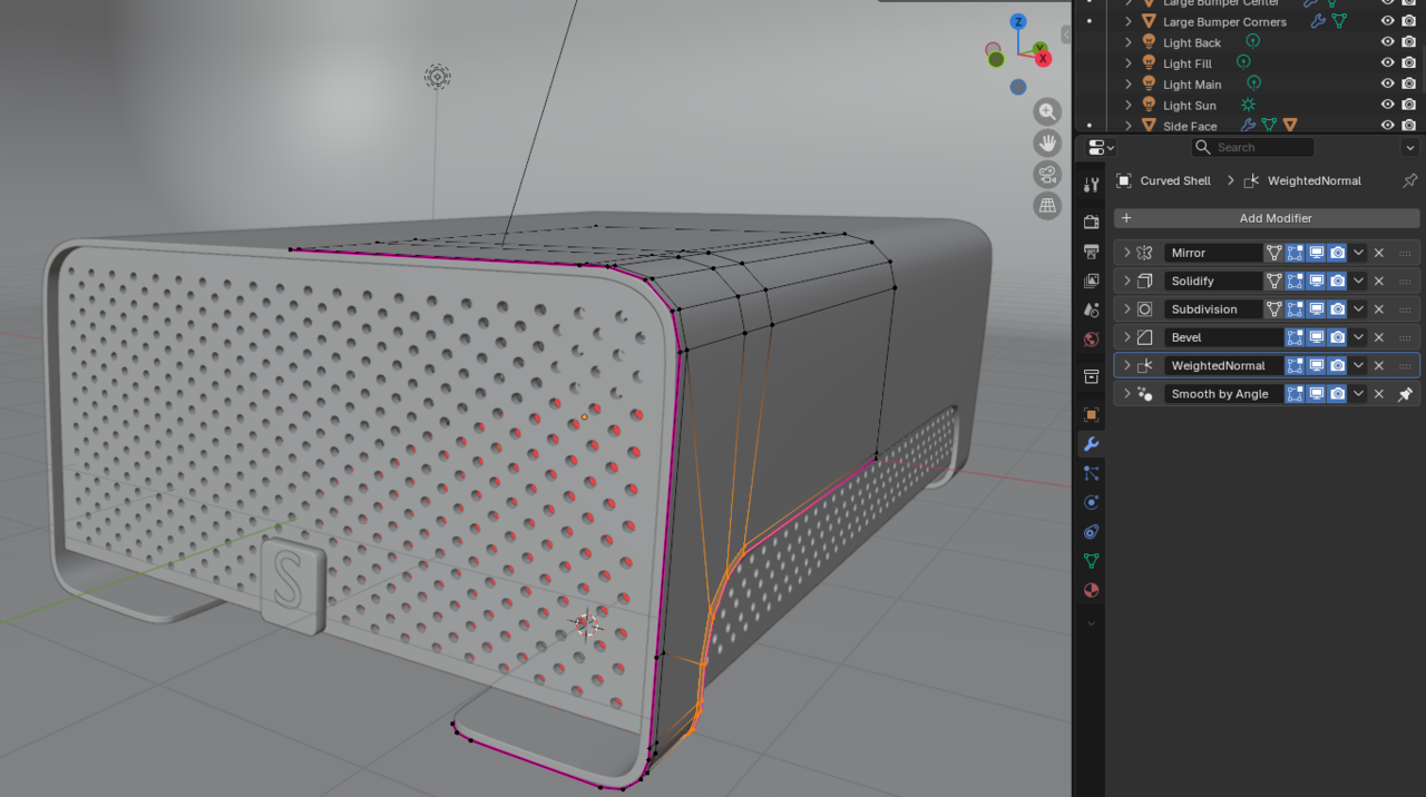
The Panels with Holes
I next set out to make the holes required for the front face and the interior side panels. I recently tried my hand at creating a diamond plate texture, so this was familiar territory for me. Blender 5.0’s new Array tool with the gizmo is incredible for this type of work! First I created a cylinder with an array that offsets it to the right and down to make a diagonal pair (blue below). A second array was made to tile that diagonal pair horizontally (red below), and a final array tiles that whole strip vertically down (green below) to fill the area with these cylinders.
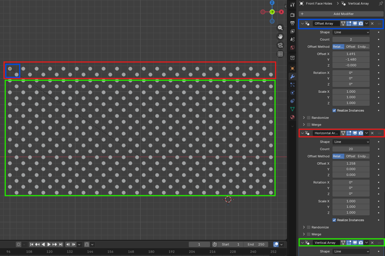
With these cylinders laid out, I used it in a boolean to cut it out of the front face. Then I added some bevels and mirrored it to make the side you don’t see on camera. All of this was duplicated exactly for the side panel.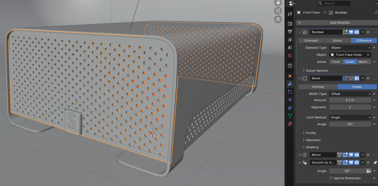
The geometry here is entirely ngons. The result here is fine since I am not subdividing this face. A lesson for later, my cylinder had the default 32 vertices, which resulted in the side face having almost 4,500 triangles! I probably should have used fewer faces, since 32 is overkill for such a small hole. My computer struggles to manipulate this boolean because of these calculations.The Glowing Letter
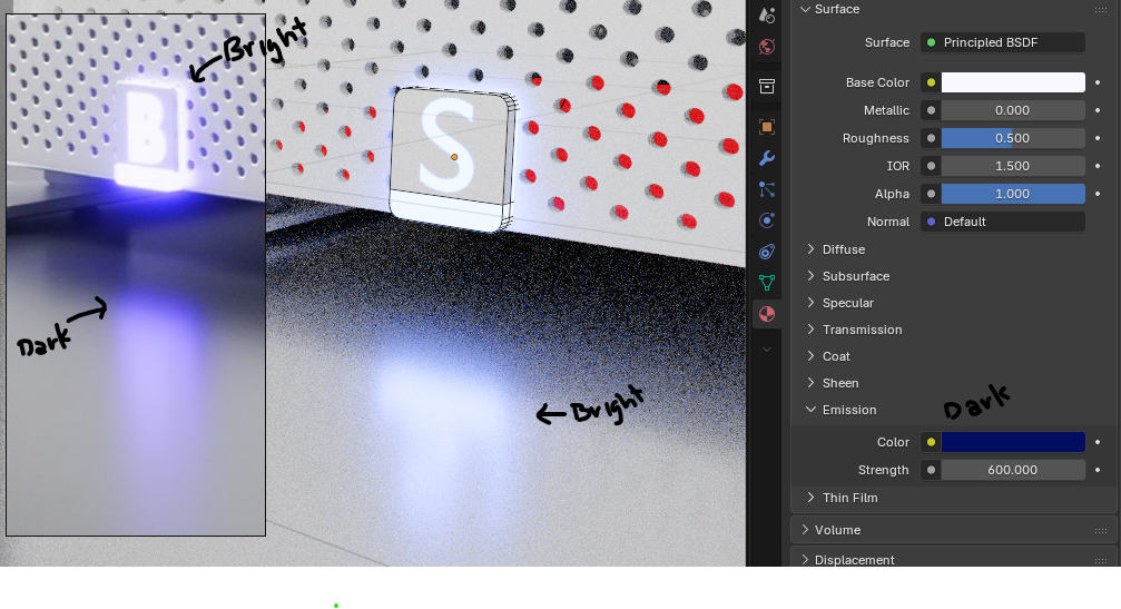
I added an S for my username. It is a separate object from the little rectangle it sits on and is still a text object that just has a solidify on it. The problem I had here was finding a simple way to replicate the reference render with the emission. I haven’t done very many textures with emission, so I couldn’t figure out how to make the texture bright while properly reflecting a dark blue light like in the original render. The cube has some manual bevels on the edges, and a bevel modifier to soften the rest of the edges, pretty standard stuff at this point. I added an edge loop to the bottom and around the side so that the light texture could be applied to those faces. I’m also now realizing that the plate should have been skinnier. Oh well!
Rendering
Another thing I couldn’t quite figure out was how the background of the original image seems to transition from a reflective surface to a rough background smoothly. My attempt was to make a curved backdrop like so, with a rough texture on the back and a low-roughness texture beneath the hard drive to get those nice reflections. When I tried the whole backdrop with a reflective texture, there were highlights from the lights.
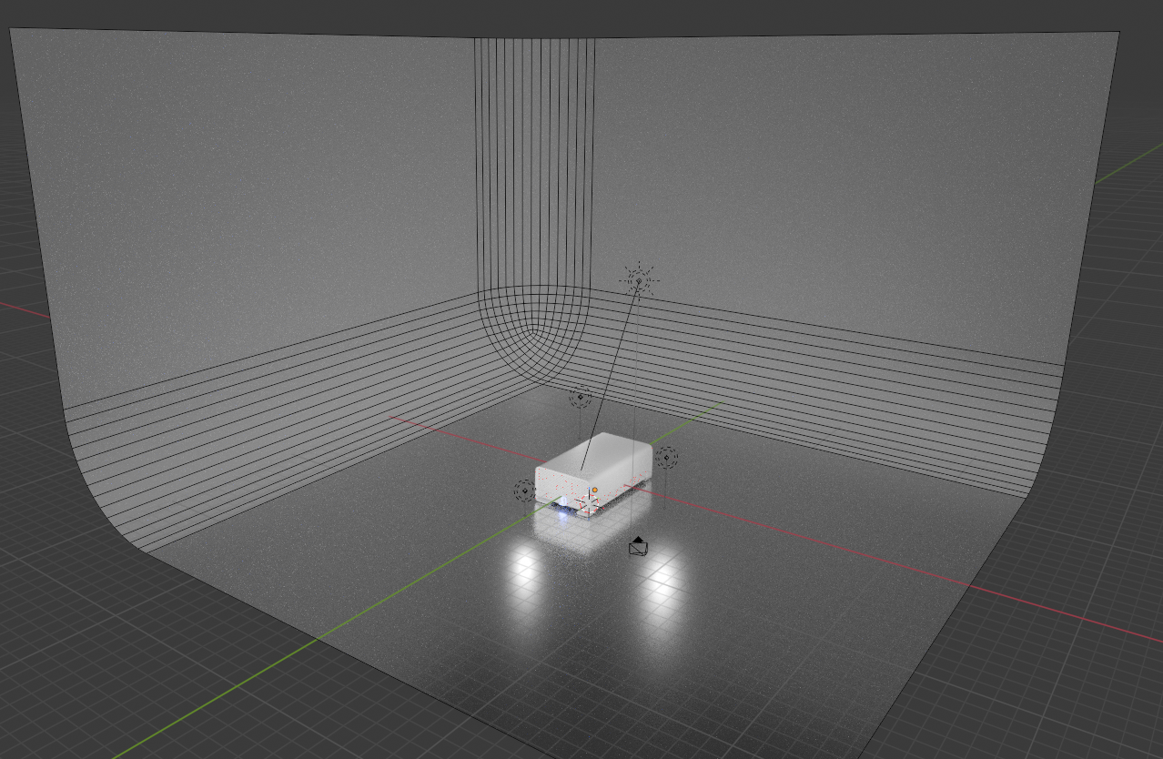
As we all know, lighting is incredibly important to making a render look nice. I attempted a 3-point lighting system, with a primary point light at 1000 power, a fill light in to the left of the camera at 500 power, and a backlight at 300 power. I also added a sun with a power of 1 to brighten the scene as a whole. I fiddled with this for a few hours, but that’s probably for a later lighting course, so I stopped. Perfection is the enemy of done, after all.Thanks for following along so far! I appreciate the feedback I have received until this point. Time to see how I went wrong by watching the how-to video.
To build upon the Soccer Ball tutorial, I made this Sci-Fi Dome. The typical place where people grow plants on different planets. The Shift-G selections used on this one were a little more fiddly, since the flattened bottom half resulted in some incomplete hexagons that I had to manually select. I used Vertex Groups a lot! The subdivision surface made the corners of the gray parts misbehave, so I used some edge weights to sharpen the edges, but that means there’s a visible point in the middle of each intersection. This would be less visible if the gray material didn’t have metallic set to 1. I think more support topology like support loops or bevels would benefit this model, but that wasn’t part of the soccer ball tutorial, so on to the next!
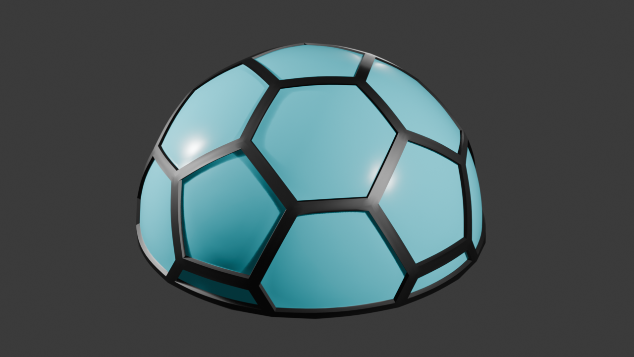
Another tutorial complete, and here is the soccer ball. I really liked this one because it contained a lot of selection stuff I didn’t know about. The entire Shift+G menu was new to me, and is a huge help! Also, setting Vertex Groups to be selected later is incredibly useful!

-
AuthorPosts
