
Why are two “Mapping Nodes” in Sequence needed for Volumetric Tunnel?
Forum Archive › Why are two “Mapping Nodes” in Sequence needed for Volumetric Tunnel?
- This topic has 26 replies, 5 voices, and was last updated 5 years, 7 months ago by
Ingmar Franz.
-
AuthorPosts
-
January 20, 2021 at 6:49 am #13365
@spikeyxxx Could you please explain why we need a second “Mapping Node” in order to stretch the “Volumetric Cloud” along “Local Y”? Aren’t the scaling operations along the three axes independant from each other?
January 20, 2021 at 7:31 am #62550If I’m not mistaken it was to do with the order in which the transforms are carried out. I’m sure @spikeyxxx will explain it better.
January 20, 2021 at 9:22 am #62551@adrian2301 Thanks, Adrian 😀! I’m also convinced that @spikeyxxx will have an excellent explanation 😀! Meanwhile, I’ve done some tests. I can achieve the same result with just one “Mapping Node” by setting the “Mapping Type” to “Texture” instead of “Point” so that it’s the texture instead of the texture coordinate system that is scaled. I just have to select a high enough “Y-Scale” so that the fog tunnel runs through the whole fog volume:
 January 20, 2021 at 9:24 am #62552
He most certainly will. I’ll be the first to admit I don’t understand the math enough to explain why this works, but here’s a GIF showing how stacking mapping nodes has a unique effect:
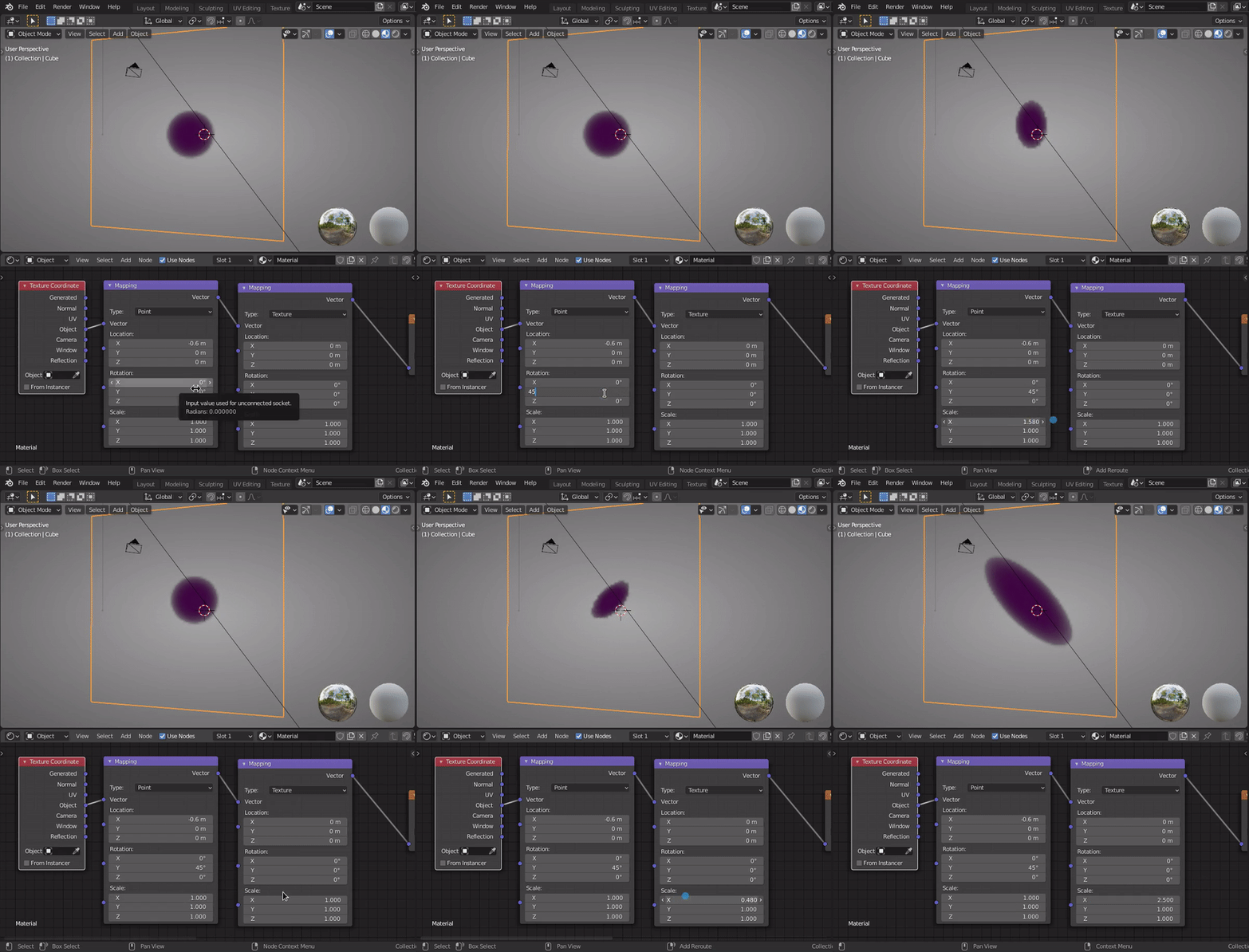
Note how the I change the first mapping node’s Y rotation to 45 degrees, yet the X-scale disregards the angle and stretches in “global” horizontal orientation. However when I adjust the X-scale of the second mapping node, it stretches in the 45 degree orientation. Similar to “local” space (I think).
January 20, 2021 at 9:30 am #62553@theluthier Ah, okay, that’s a good point 👍! I didn’t take into consideration the case of a rotated cloud. But in this case, it would seem to me better, if the Blender developers would place the “Rotation” fields in the “Mapping Node’s” layout below the fields for the “Scale” in order to signalize what’s calculated first.
January 20, 2021 at 9:35 am #62554I’ve just tested the rotation with my “One-Mapping-Node-Setup” and found that it’s taken into account :
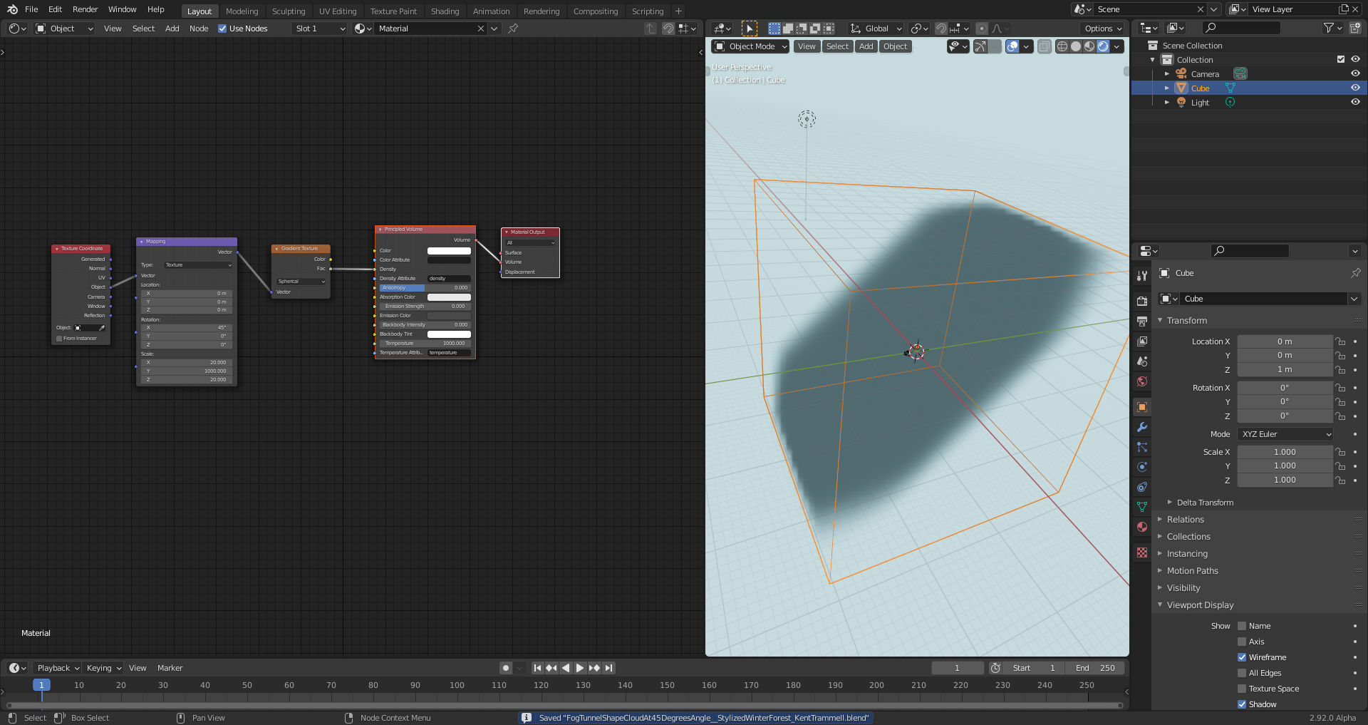
@theluthier A little bit off topic: How to you create the screencasts since this is no longer supported by Blender?
January 21, 2021 at 3:00 am #62555Sorry for the late response.
The order in which the transforms are done are Location, Rotation and Scale (with the default Point Setting).
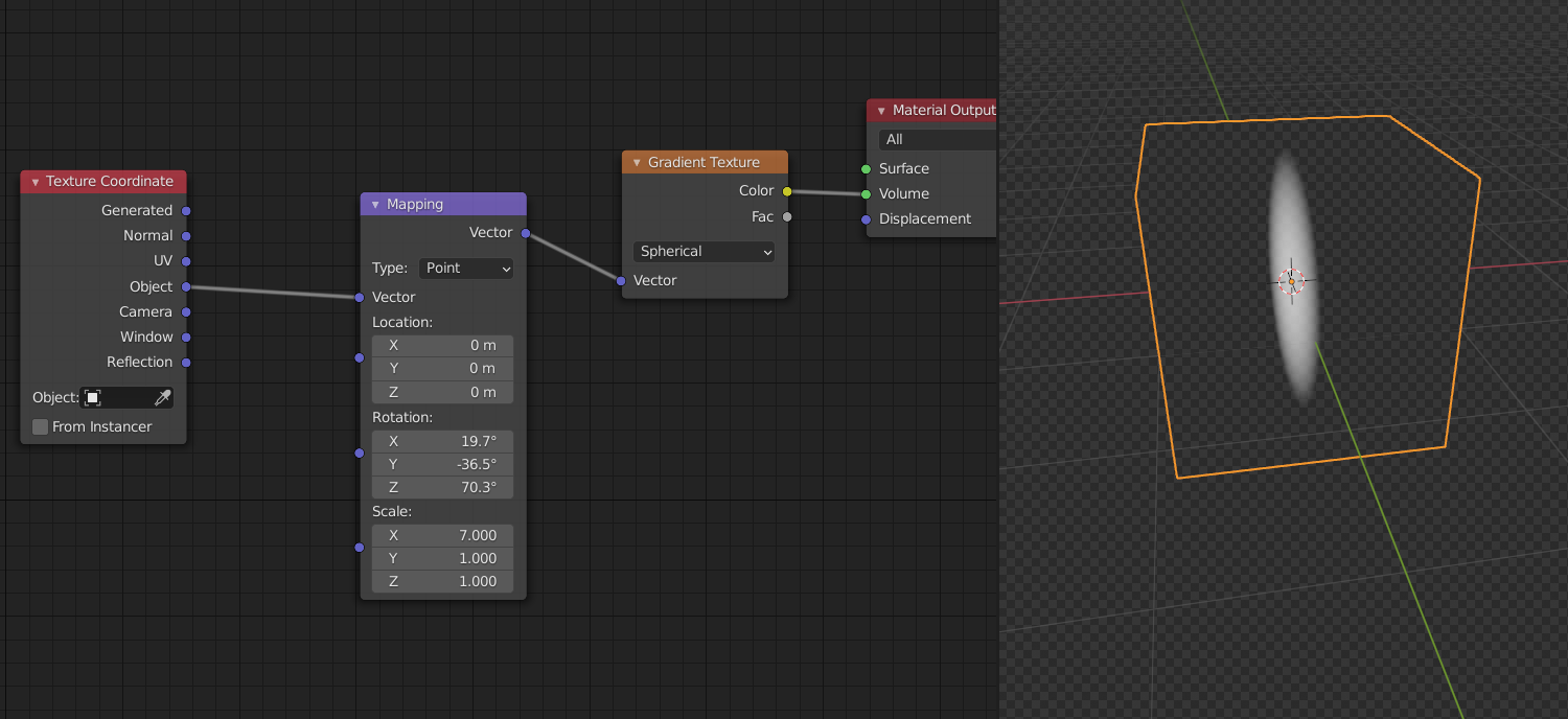
Here you can see that the Rotation is done first (on the sphere,thus having no visible effect) and then it is scaled along the X-axis:
 January 21, 2021 at 3:17 am #62556
There is an excellent course here on CGCookie that explains how the Mapping Node works:
https://cgcookie.com/course/working-with-custom-transform-nodes-in-cycles
Personally I would always use two Mapping Nodes in the above case, because it is more intuitive,I think and also, changing the setting from Point to Texture means Blender makes a matrix multiplication under the hood for each point in 3d space, before performing the mapping transforms. Now the Rotation is also done via a matrix multiplication, so with one Mapping node you have two matrix multiplications (which are quite ‘cheap’ by the way ), with two Mapping nodes (left at Point) you only have one matrix multiplication. Surprise!
Point is a bit of a vague term here, but what it means is that every point in 3D space is transformed.
Changing the Location is just adding the same vector (the one you fill in in the Location field) to each point in 3D. (The ‘name’ of each point, meaning the coordinates, depends on the Texture Coordinates you are using.)
Changing the Rotation is performing a matrix multiplication on each point and changing the Scale is term by term multiplication of the vector and each point.
January 21, 2021 at 8:59 am #62557@duerer My linux distro (Deepin) has an awesome screen capture tool for quickly recording parts the display at any resolution. But OBS will work fine too, just requires more setup. Once I’ve recorded a short video I convert it to a GIF with this website.
January 21, 2021 at 9:27 am #62558Correction!
I was apparently wrong.
According to the Manual:
with Type set to Point, the order is Scale, Rotate, Translate.
When set to Texture, the order is Translate, Rotate, Scale.
However, as can be seen in my screenshot, I cannot rotate the scaled sphere. I do not yet understand why; this needs further investigation.
January 21, 2021 at 11:14 am #62559Thanks @theluthier for this tip 👍! I’ve found a plugin named “GAP” for GIMP 2.10 here for converting a video into images that can be further converted within GIMP into animated GIFs. The plugin is now installed but I haven’t tested it yet.
January 21, 2021 at 11:21 am #62560Thank you, @spikeyxxx, for your efforts 😀👍! This behaviour of the “Mapping Node” is really strange 🤪.
January 21, 2021 at 11:32 am #62561Okay, I found the problem!
What is happening is the way the spherical Gradient is calculated is by using the length of the vectors.
Say, you use the Scale of the Mapping node to, say scale all the points by (3, 1, 1).
This means that the point (1, 0, 0) becomes (3, 0, 0). Now rotate this point 90° around the Z-axis, for instance. This makes it (0, 3, 0). This means that the length of the vector (1, 0, 0) after scaling is 3, but rotating that vector doesn’t change that length.
Use any other Texture (for instance a Checker Texture) and it works as you would expect.
January 21, 2021 at 12:07 pm #62562@spikeyxxx I still don’t understand why the “Rotate” settings in your example here have no effect. And why is the order of the three transformation types important? Also still confusing to me is that “Point” and “Texture” have different orders for these transformation types. Unfortunately, I’m not familiar with Blender’s source code.
January 21, 2021 at 1:11 pm #62563Yes @duerer I was afraid that I wasn’t clear 😉
I am also not familiar with the source code btw.
Important is the fact that it is not the Mapping Node that is causing troubles in my example with the scaled sphere.
Let’s first focus on the Mapping Node.
When using the Point setting, each point in 3D space is being transformed by scaling (call this S) rotating (let’s call this R) and translating (moving, let’s call this T). A point P in space is then transformed into: T(R(S(P))). Scale the point (/vector), then rotate it and then translate it.
Some numbers:
let P be (x, y, z), then scaling by (3, 2, 1) will transform this into S(P): (3x, 2y, z). Followed by a rotation of 90° around the Y-axis will transform this into R(S(P)): (z, 2y, 3x). Translating it then by (1, 0, 0) will transform this point into T(R(S(P))): (z+1, 2y, 3x).
Now we plug the Mapping Node with these transforms into a Texture Node. Whatever color this texture has at (z+1, 2y, 3x) will be put at (x, y, z).
Now let’s try and get that same effect with the Mapping Node set to Texture.
So, we want the point (z+1, 2y, 3x) of the texture to go to point (x, y, z) of the coordinate system. We do this by inverting the transforms and inverting the order (this is sometimes called the socks and shoes theorem):
We get: S`(R`(T`(P))).
Recall that:P is (z+1, 2y, 3x), so T`(P) is (z, 2y, 3x). R`(T`(P)) becomes (3x, 2y, z) and (scaling by (1/3, 1/2, 1)) will gives us: S'(R'(t'(P))) which is (x, y, z).
Does this make any sense to you now?
-
AuthorPosts


- The topic ‘Why are two “Mapping Nodes” in Sequence needed for Volumetric Tunnel?’ is closed to new replies.