
Loops changing direction without poles
Forum Archive › Loops changing direction without poles
- This topic has 17 replies, 3 voices, and was last updated 4 years ago by
Omar Domenech.
-
AuthorPosts
-
August 7, 2022 at 12:56 pm #15360
At 7:36, Jonathan starts explaning that each time a loop is “changing direction”, a pole is going to appear. I understand all the cases that are shown in the video, and for very exagerated changes in direction, this seems to be totally true.
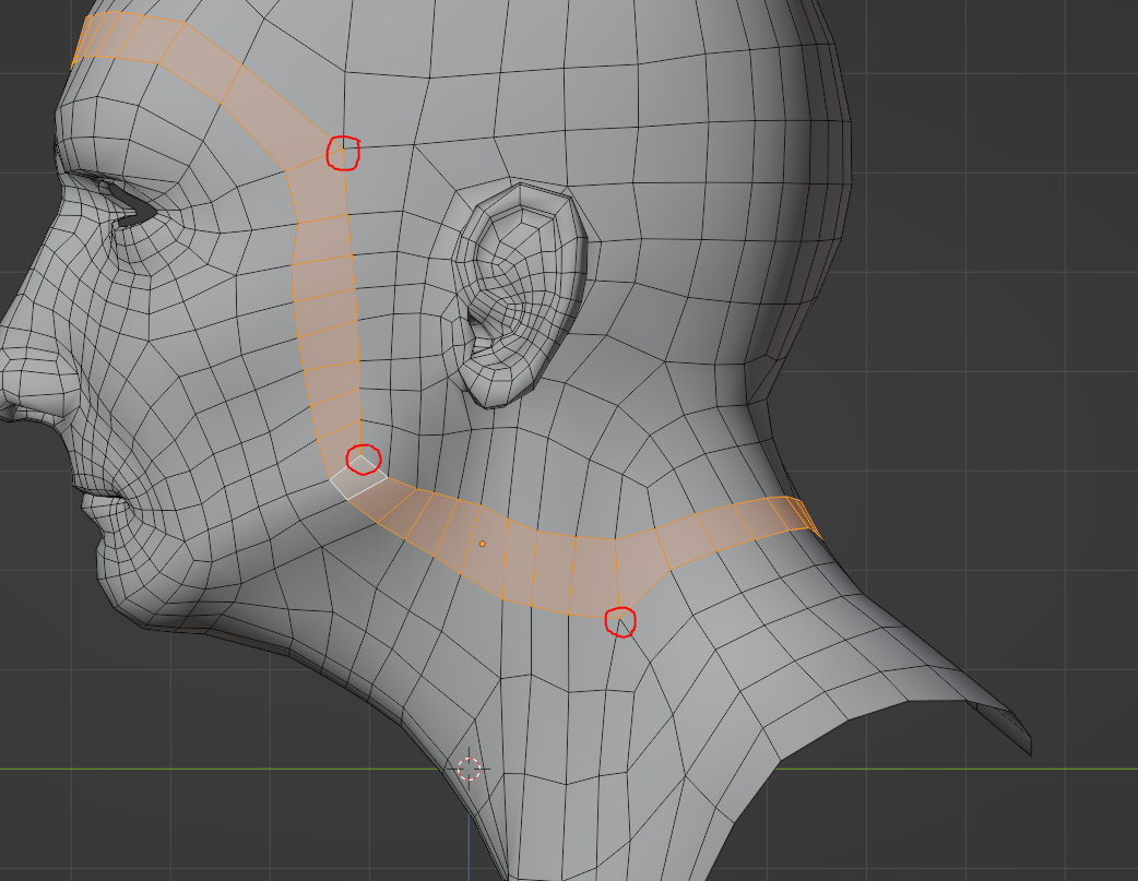
However, It seems like I’m missing some piece in my mental puzzle. What happens when the change in direction is very subtle? I don’t see any poles in these cases, such as below.
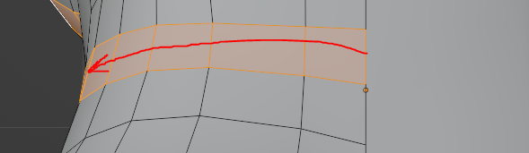
I don’t have very good pulse, but it’s clear that the red line is not horizontally straight, but slightly curved (so there are changes in direction in these cases, but no poles).
Another example, this is not straight at all but there are no poles in this section.
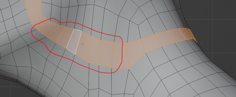
So what I’m not understanding?
Thank you in advance!
August 8, 2022 at 1:56 am #75106Hi @Carrascado ,
Tha’s a good question; it comes down to what a change in direction is. This:
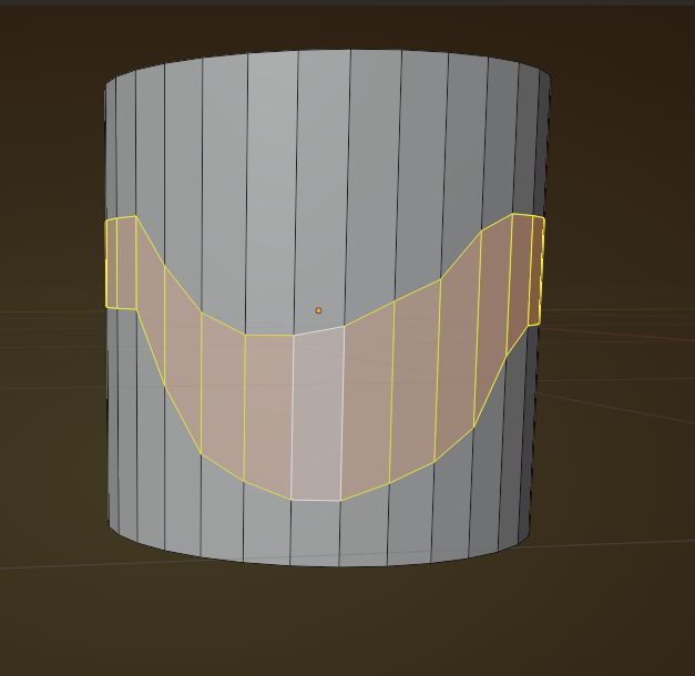
is not considered a change in direction. It obviously isn’t straight, though.It is a bit like when driving on a road that bends; you are not changing direction (a very incomplete analogy, I know…).
You really have to look at the model; when a loop goes up along the side of the face and then changes direction to go across the forehead, that is changing direction:
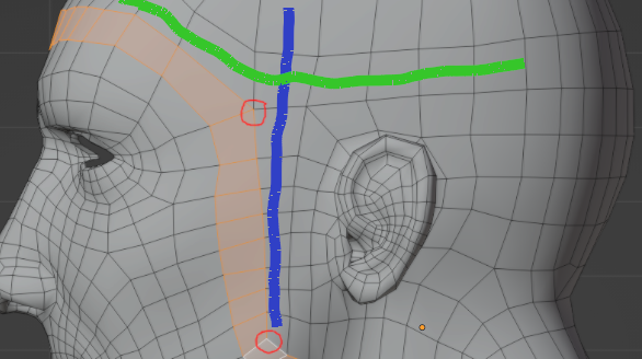
The blue line shows the side continuing and the green, the forehead continuing.
Not a perfect explanation, but I hope it helps a bit.
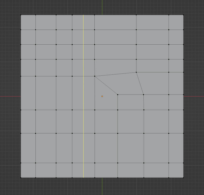
August 8, 2022 at 6:44 am #75107Hello Cristian. Yes, as Martin says, the direction change is not only visual per say. Those examples you have go straight, even though you visually see them distorted. If you ran an edge loop in your example, you would see how they go straight without turning. For example, you can see how in these sets of faces the loops runs straight:
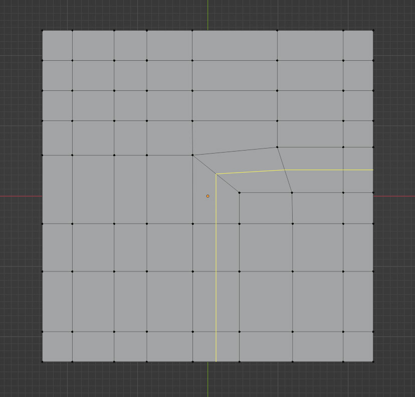
But if you tried a loop on the other faces, it’ll turn instead of going straight:
I mean, it could do this:
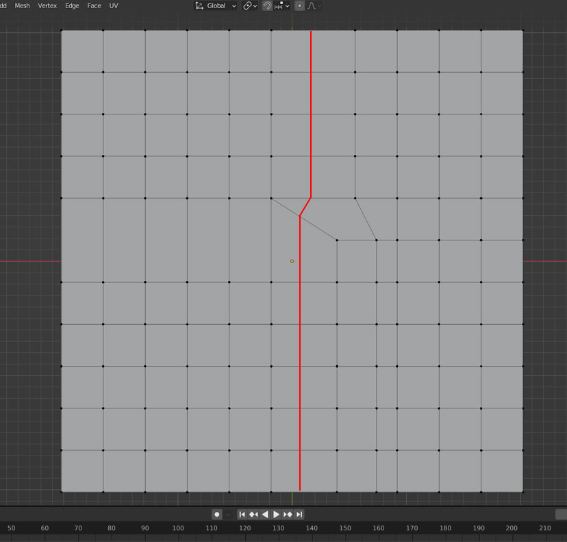
But it doesn’t go that way, it “turns”. There’s the pole, with 5 edges connected. We say turn, but it’s just that the faces the loop wants to go next happen to be that way.
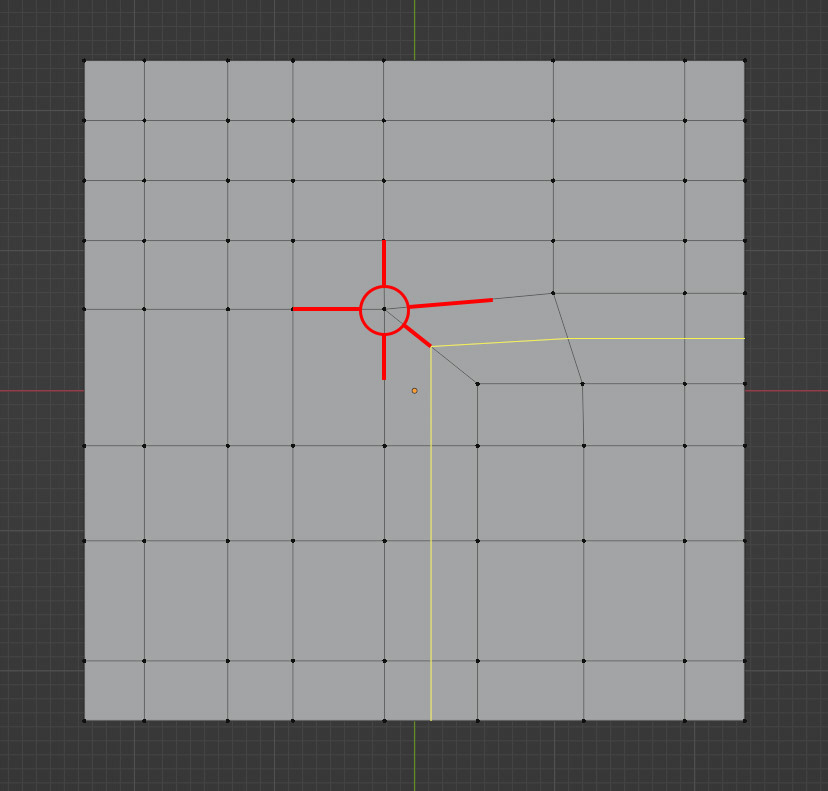
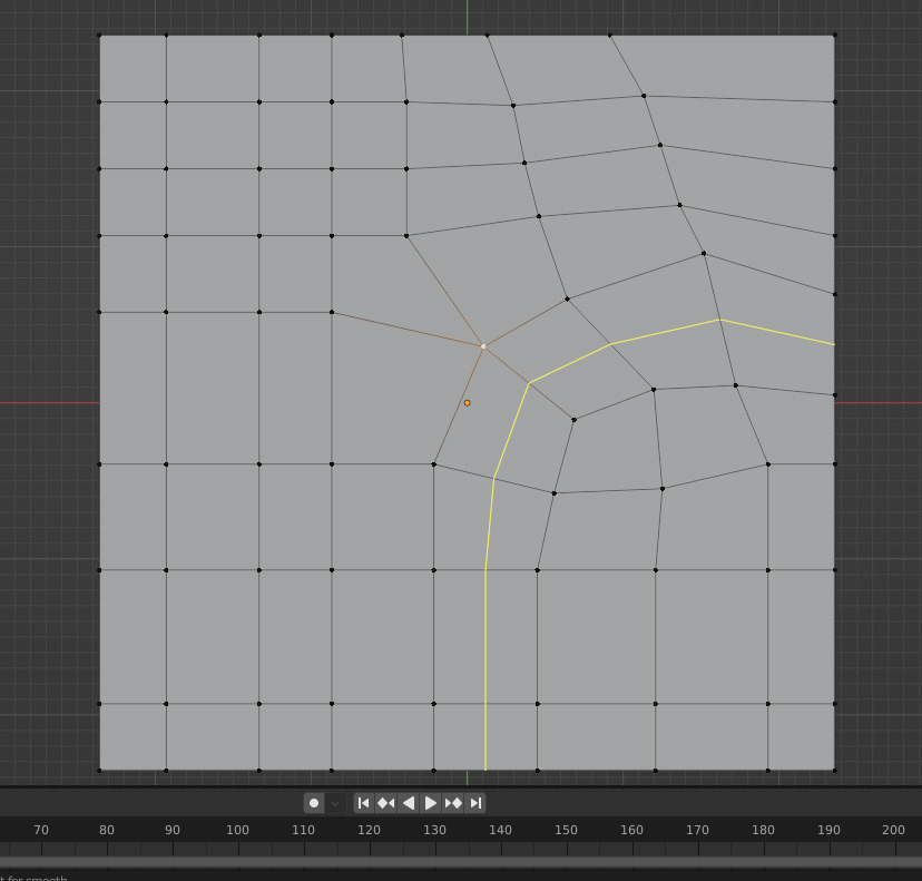
It’s clear there that it’s a change in direction, but I can take that same shape, not change anything and just move the vertices around and have it look more like a curve. It would seem like it’s straight, but there’s still a pole there, so it is actually changing direction:
And this one, even though it visually looks as if it’s turning, it’s actually going straight, there’s no poles, the faces go one right after the other:
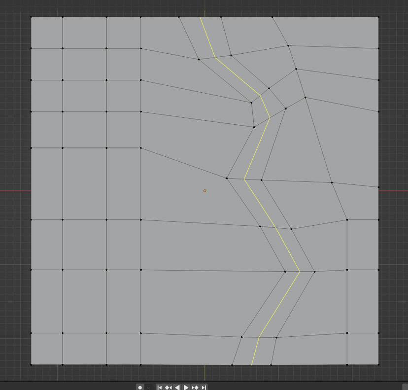
The loops is consistently going through each sets of faces in a straight line, not finding any poles that make it “turn”. It is not a visual thing, but more of how the loop behaves as it is finding it’s away through each faces.
Hope that helps. If you have further questions, don’t mind asking them.
August 8, 2022 at 9:41 am #75108Thanks Omar for the extra explanation!
This is something that is pretty hard to explain and I think your pictures really enforce the underlying ideas!
August 8, 2022 at 11:17 am #75109Hello Omar and Martin, and thank you for the responses!
It sheds some light, but I’m still not sure I understand this. Maybe I’m even more confused in some aspects haha
Is this straight because there are no poles interfering this loop? Very hard to see something straight there.
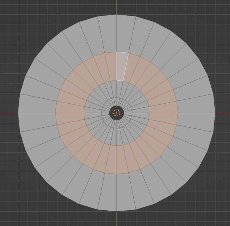
Where is the change in direction in this cube?
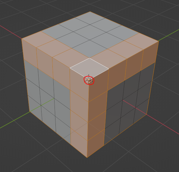
If we say the change in direction in the cube above is because the loop passes from being in the upper face to the side faces (or viceversa), doesn’t the same happen without poles here below?
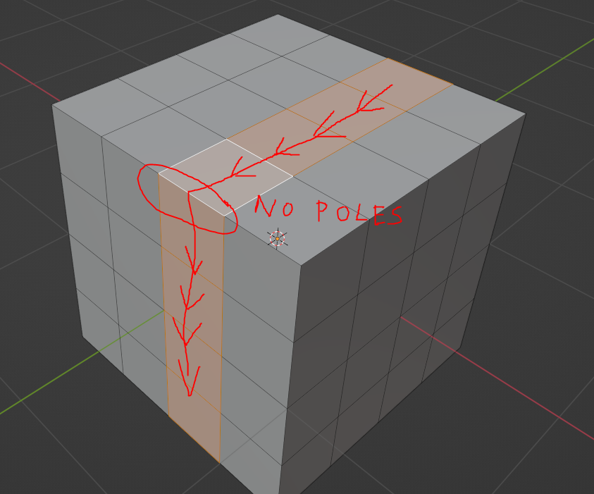
This is what puzzles me:
* When I see poles, I see changes in direction in the affected loops.* But when I see changes in direction (at least in my view), it’s not guaranteed for me to see a pole causing it.
Thank you in advance!
August 8, 2022 at 12:02 pm #75110Hey Cristian,
we are not talking about straight lines!
in your subdivided Cube example (middle picture), there are three loops around the corner of the Cube (3-sided pole!):
Does this help?
August 8, 2022 at 12:15 pm #75111As I look at it, my previous answer will probably not help at all…
Important: it is not about being straight!
It is the underlying geometry, that decides, if you are changing direction, or simply bending..,,
August 8, 2022 at 2:18 pm #75112I’d say it’s all about what path the loop takes and where you want it to go, and NOT how it visually looks. The where you want it to go is crucial I think. For example, you have this weird thing as a mesh:
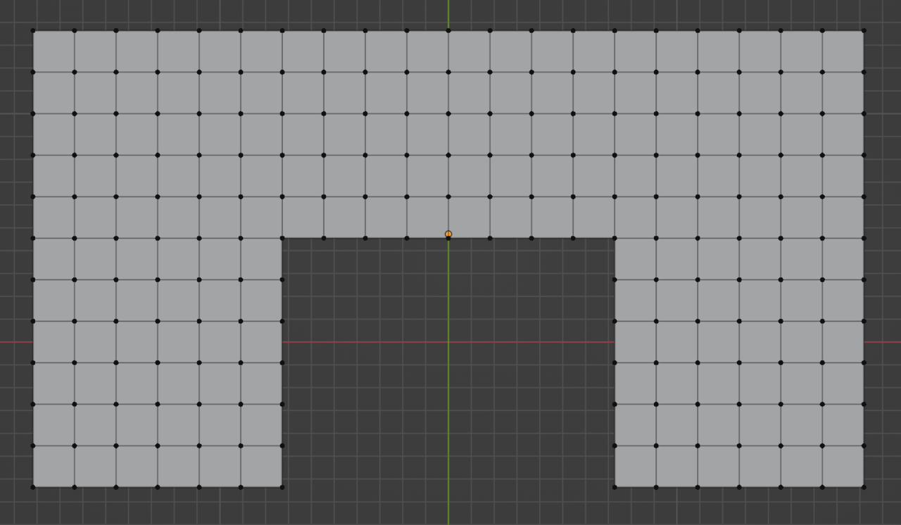
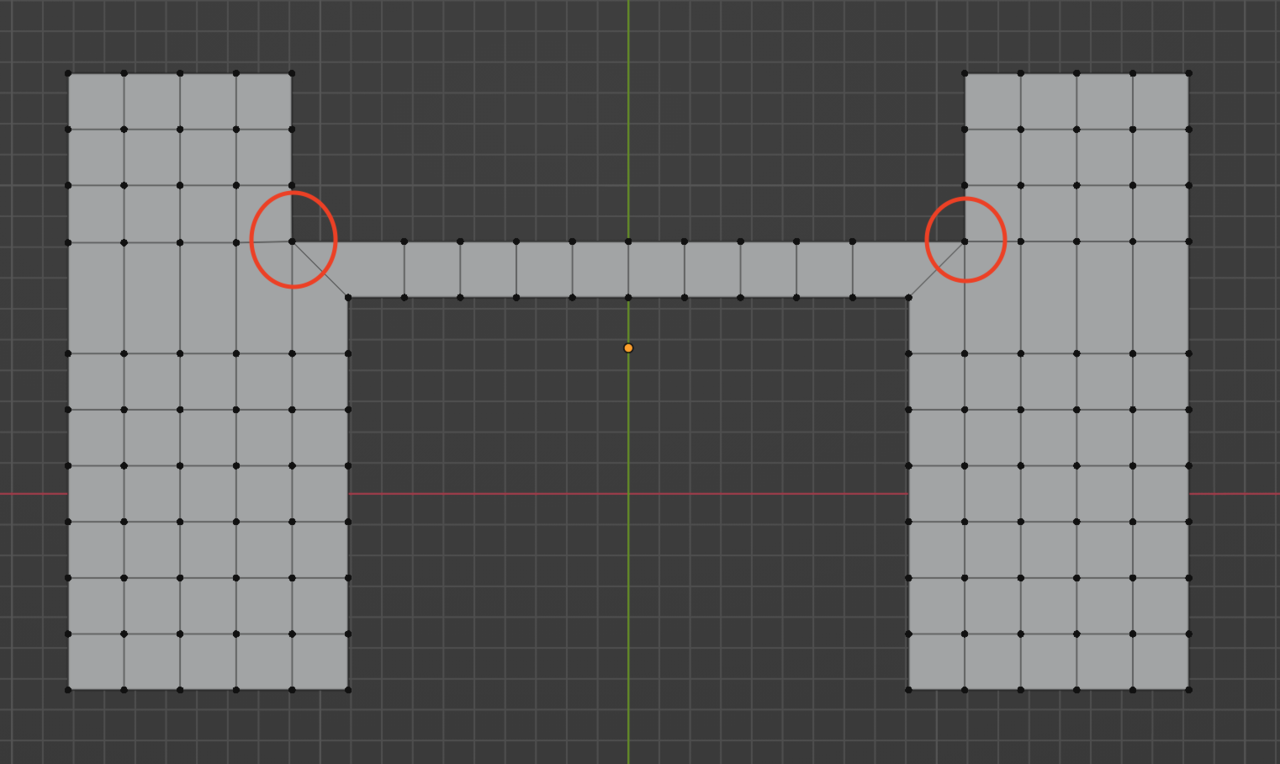
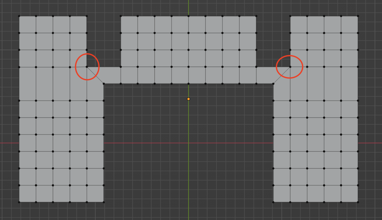
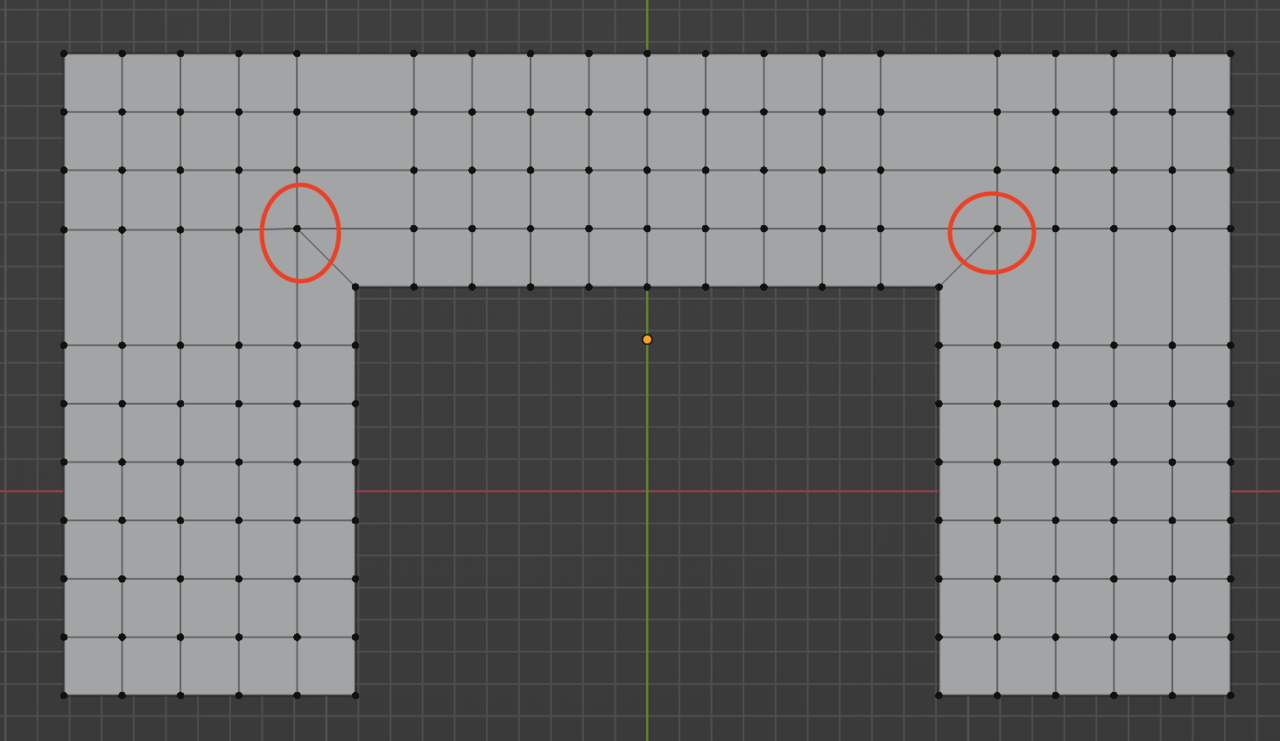
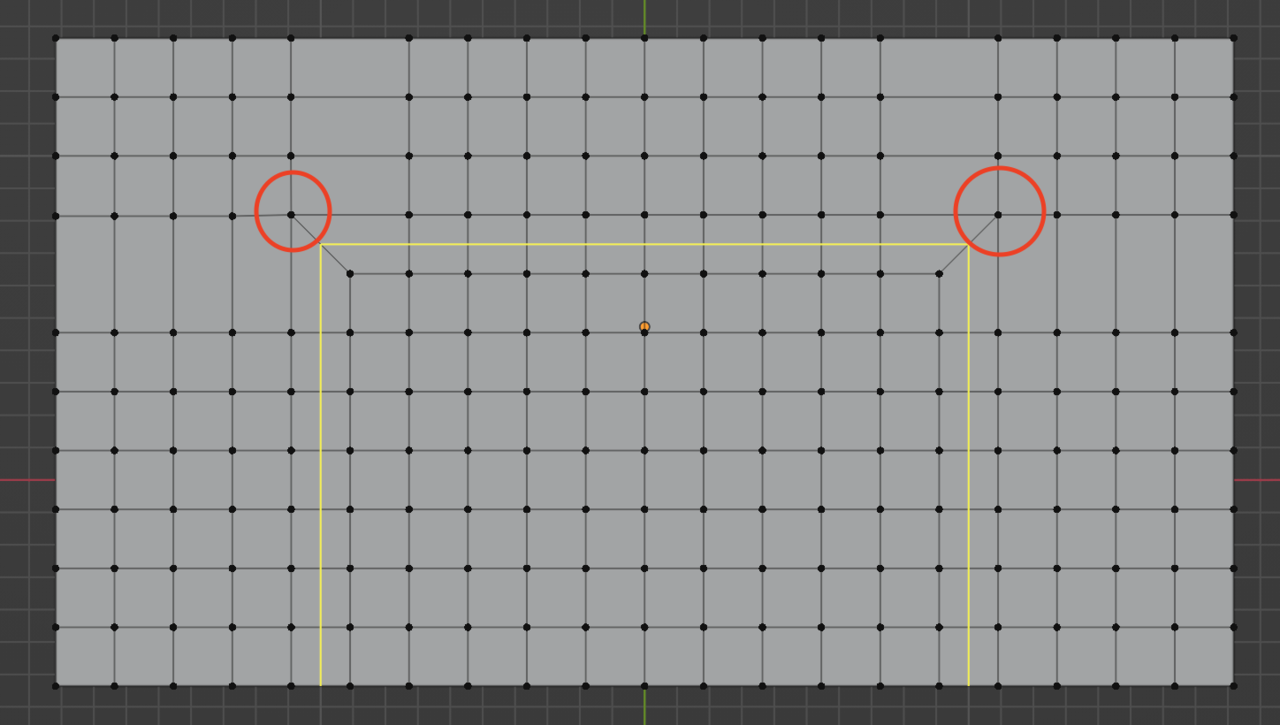
And I want the loops to make U-turns. Like this:
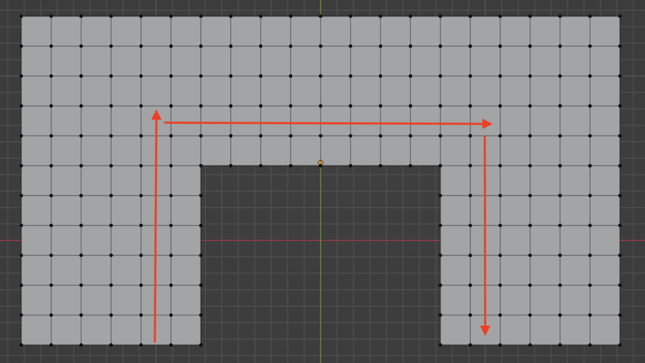
But you’ll find that when you position your mouse with the edge loop tool on on those faces, the loop will just want to go on in each case:
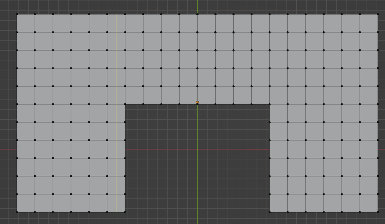
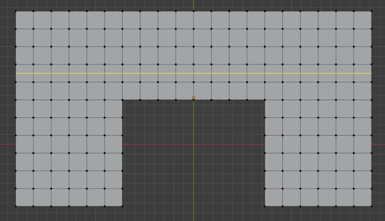
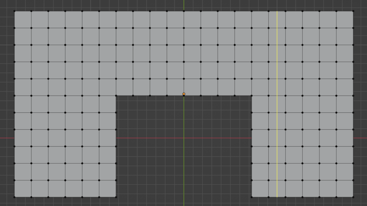
So the way to make them turn is by forcing the loop to follow the row of faces I want them to, and that is with a pole that marks the point where I tell the geometry to make the turn:
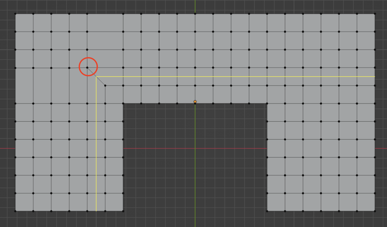
That one first, now the other one:
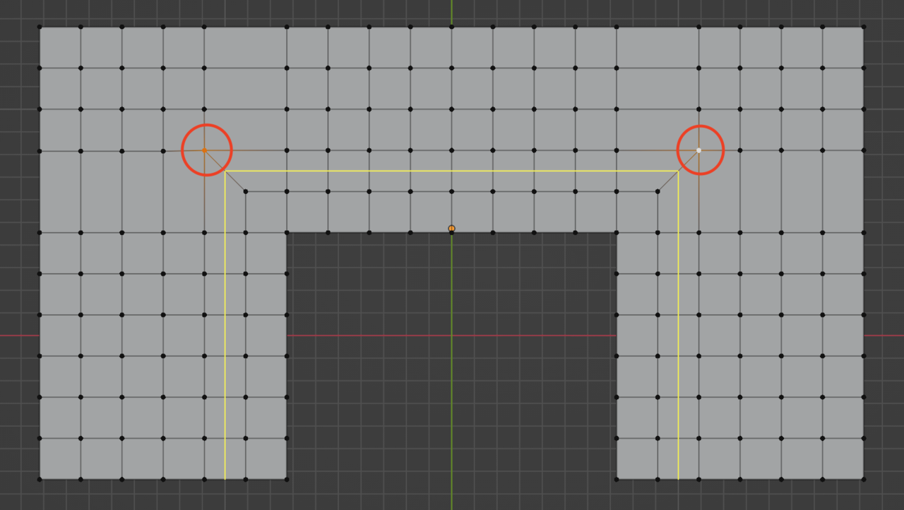
So as you can see the loop is “turning there where I want it to.
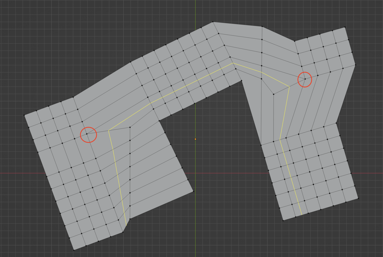
Now I can come in and make a mess out of the shape, turn it and twist it and commit some humans right abuse on the mesh and it will visually look very different, but from the loop’s points of view it’s the same, he is just following one row of face after the other until it either has to stop because of a Ngon or a triangle, or turn because of a pole. Where the pole is it will “turn”, it will not follow the straight path it had before. But as you can see to “turn” here from a visual sense, to your eyes it’s difficult to comprehend:
Maybe imagine it deconstructed like this:
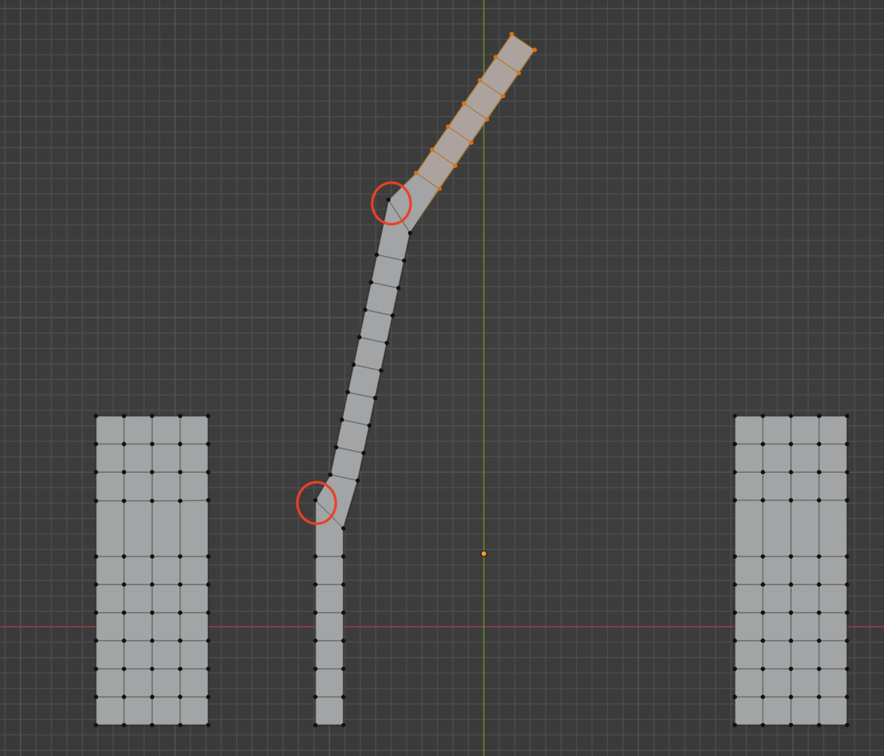
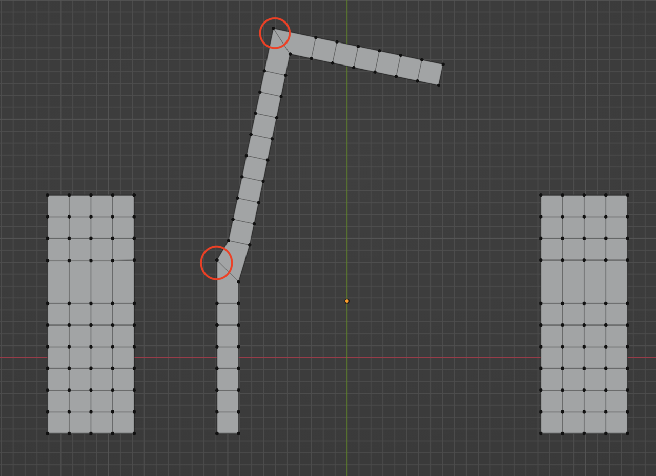
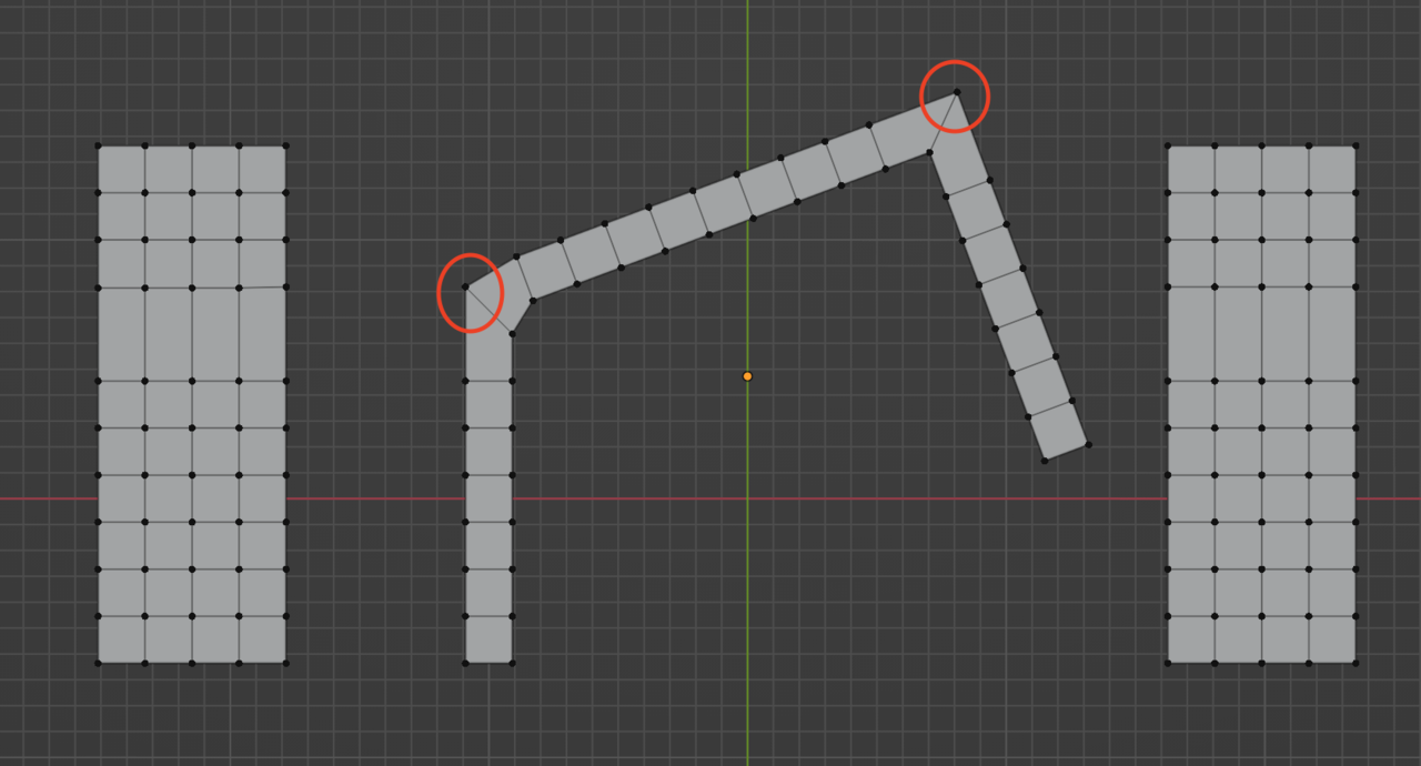
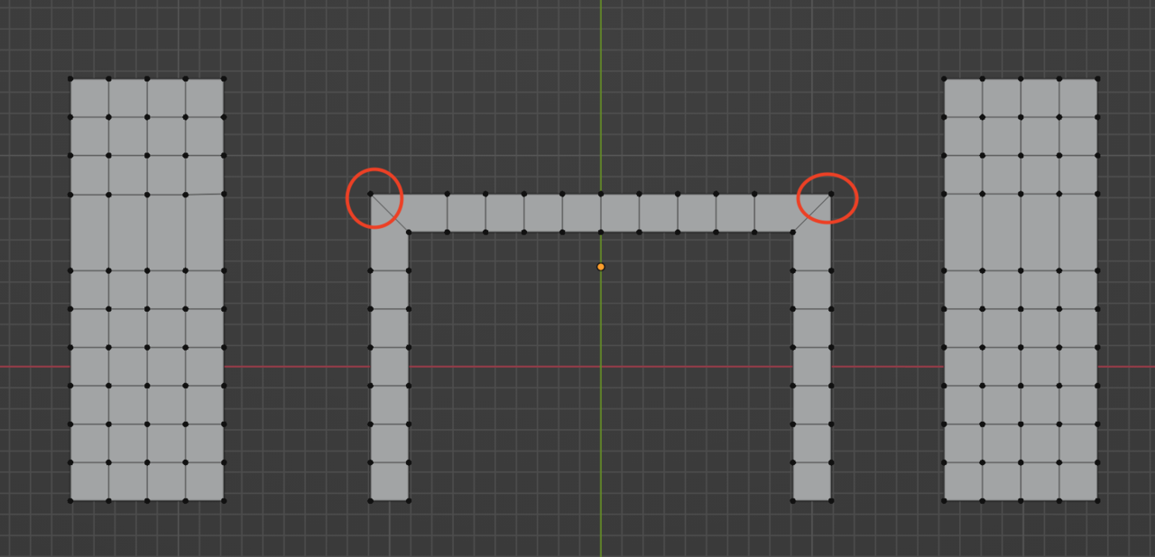
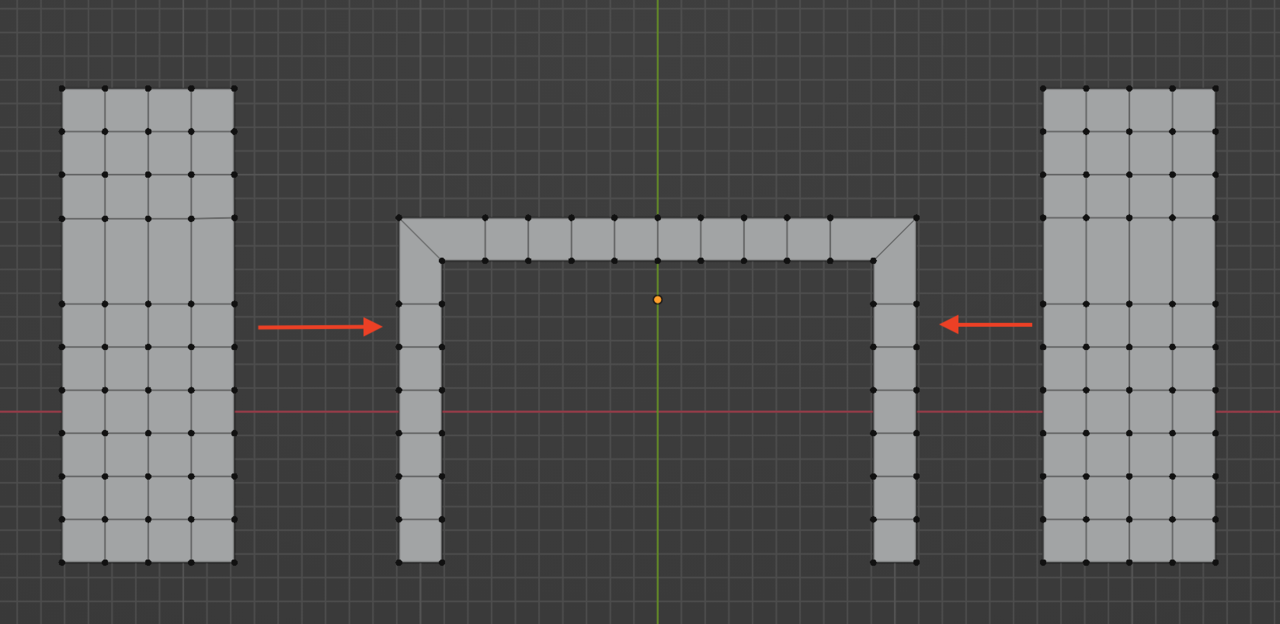
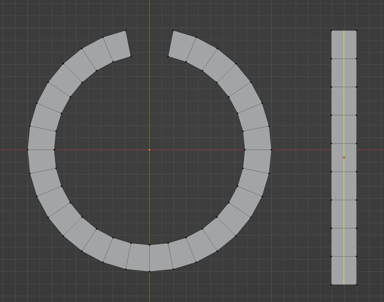
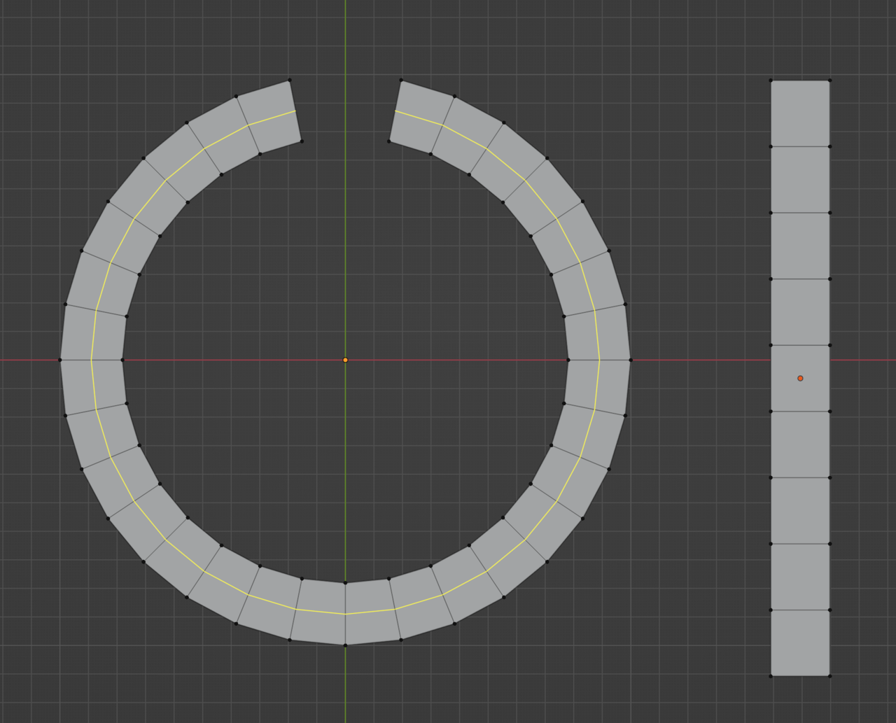
The example you have on the circle the answer is: Yes, it is basically a straight line that the loop takes, just wrapped around itself. it’s just visually not straight, but it is going straight from the loop perspective. Imagine that straight stick wrapped in on itself, it’s have the shape of a circle yes, but the loop is still going straight as it were. It is not the visual aspect we call going straight, it is the loop going on and on and on.
 August 8, 2022 at 2:36 pm #75113
With the cube example is practically the same. It is actually going straight if you interpret it from the loop just going one face after the other:

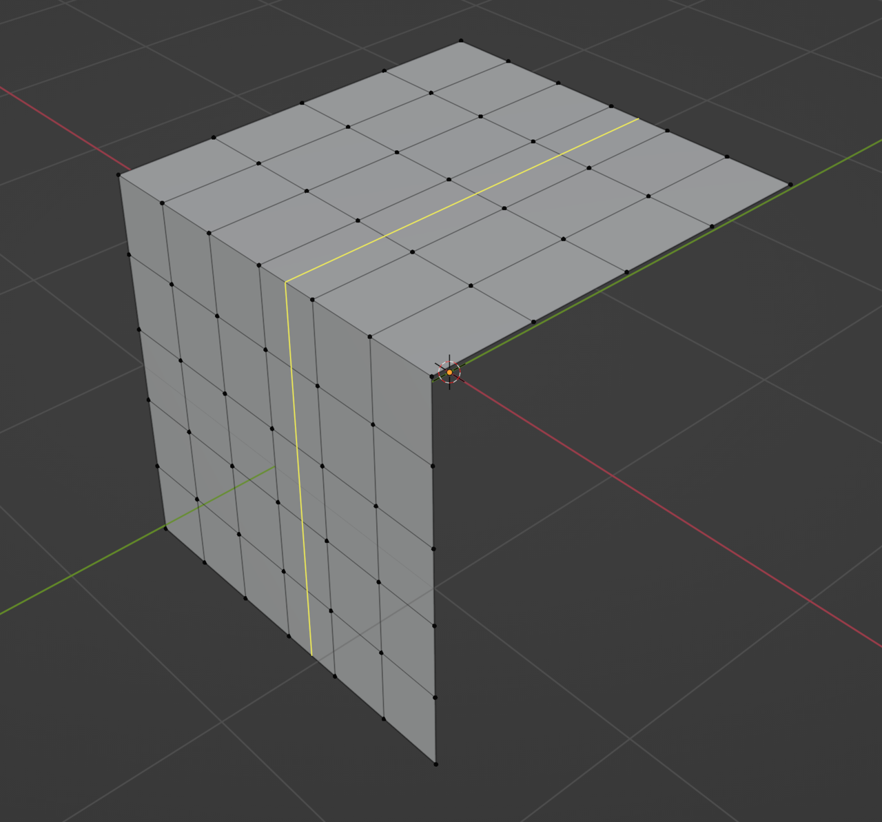
Just because the mesh bent, doesn’t mean the loop took a turn. It is not turn on the literal sense of the word. In that example, the loop is still going in a straight line.
Now see when I put a pole on the surface of the cube there… now it does actually make a “turn”
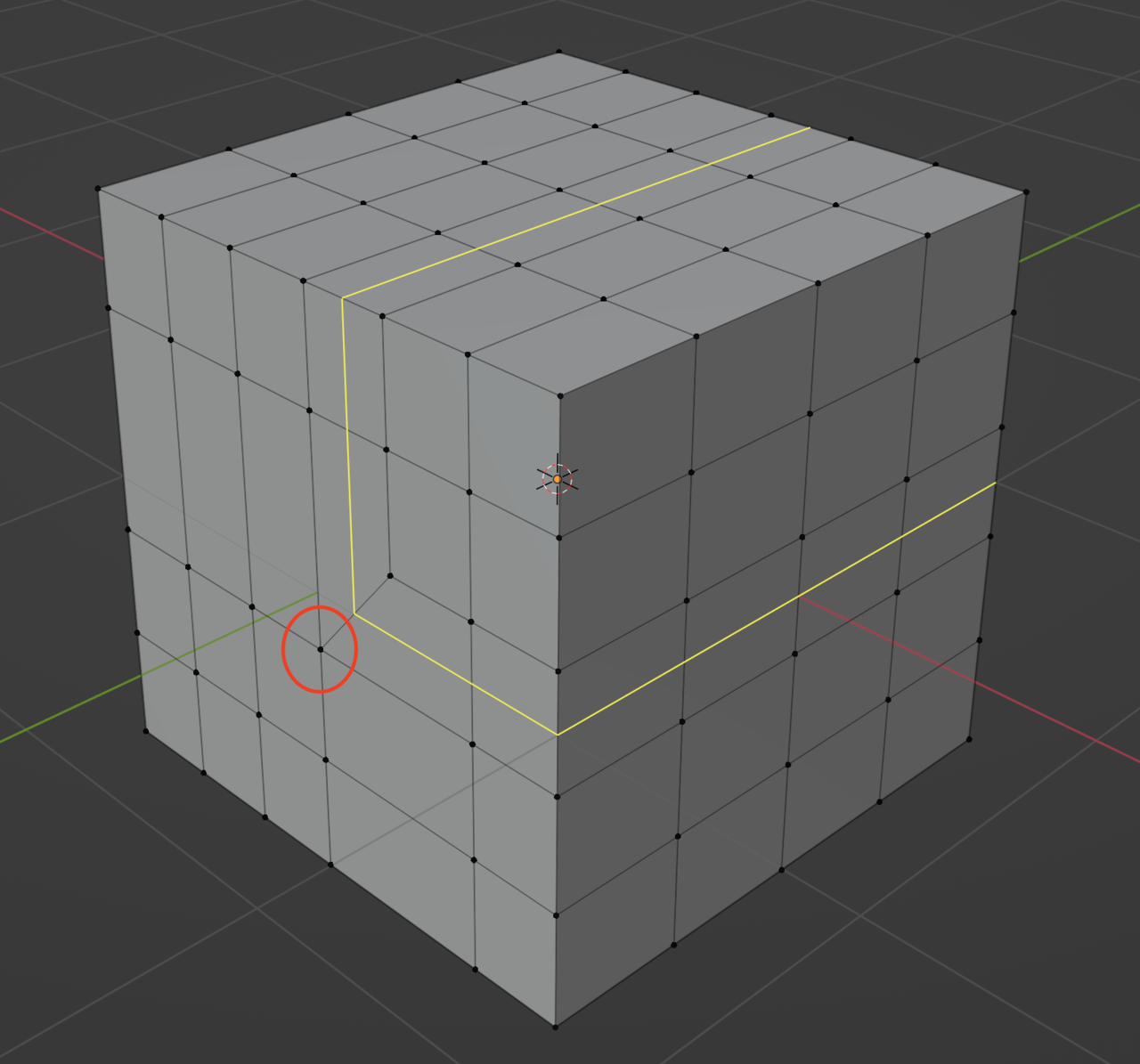
And you’d think this part “turns” as well…..
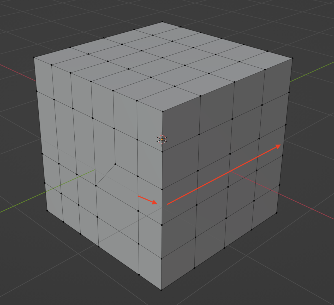
But it actually doesn’t. Visually you’d think so, but it’s not a turn just because you see it with your eyes bend. See what it is actually happening if you interpret it this way:
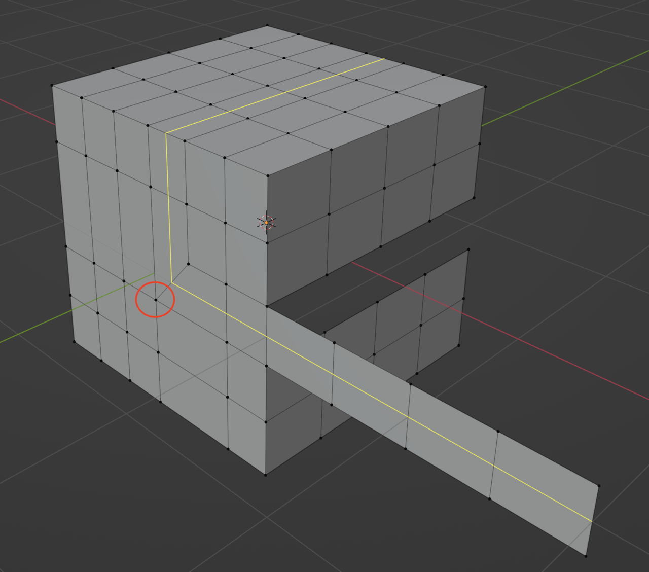 August 9, 2022 at 11:04 am #75114
Hello Martin and Omar. First of all, thank you for your patience and your answers, they are helping me a lot.
I think I’m starting to understand the idea, so topologically speaking (it might be visible or not geometrically), all loops seem to have some “flow” they follow. Until a pole “breaks this flow” and forces the loop to start another direction/flow. Is this the idea?
I think I understand all the examples posted here except for one, the cube’s corners (which are three sided poles).
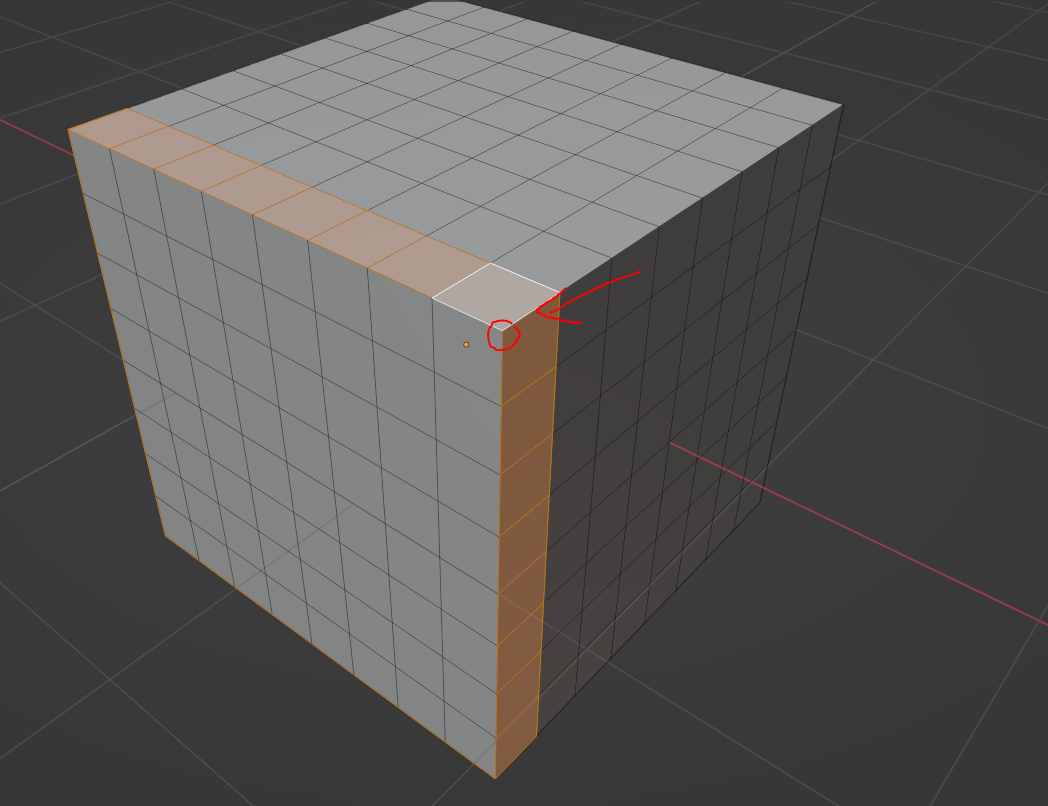
It’s very hard for me to “see” what direction is being changed here. I tried “2D unwrap” these 3 faces of the cube so it would be clearer to see (please ignore the proportions since they are not correct, but it helps me to see the “idea”).
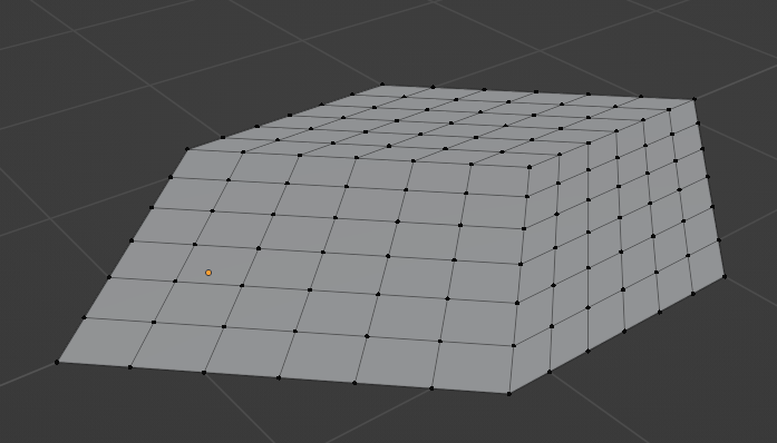
From the top view, I guess this is the direction that is getting broken.
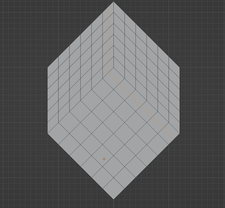
But what confuses me a lot is that this seems to happen when there is not a pole, such as here below:
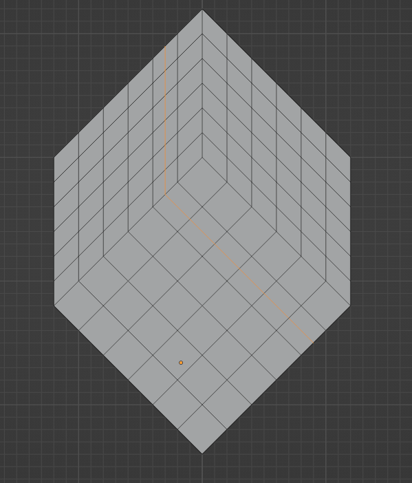
The pole seems to do absolutely nothing. I know I’m objectively wrong but this is what my mind sees and If I tried to clean up the mesh deformations of all the loops I would get this.
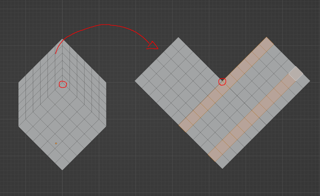
At the right I have two loops, one with the pole and the other without a pole. Both seem to be using the exact same direction. What is the difference?
Thank you in advance!
August 9, 2022 at 11:39 am #75115Hi Cristian,
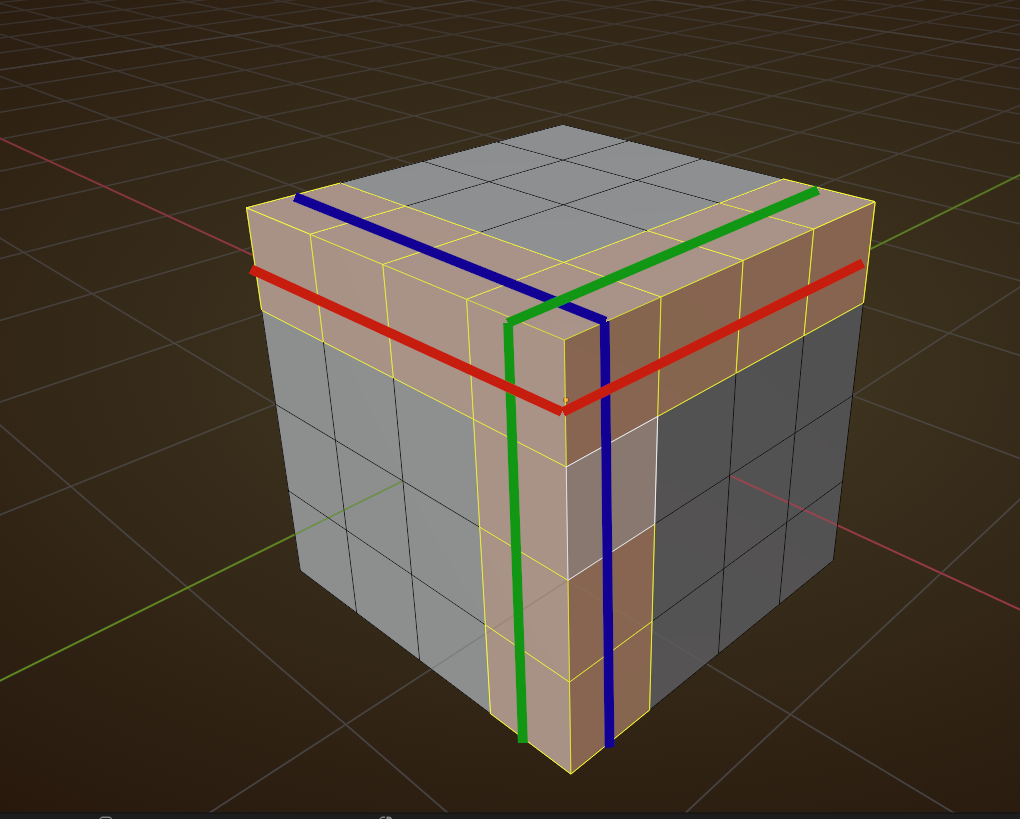
That one is also the most complicated…If you care to look at my picture of the Cube:
then starting at the bottom corner, you see that the green and blue lines start out being parallel, and the they cross over one another and go their separate ways, no longer being parallel!
This means that at least one of them has changed direction.
However, you can consider the green line to go straight and then the blue line has changed direction, or the blue line goes straight and then the green changes direction…or both change direction…
This happens all the time in traffic…you can have a Y-crossing and one direction is considered going straight and the other is changing direction…or on a roundabout, going around is considered going straight, and leaving the roundabout is changing direction.
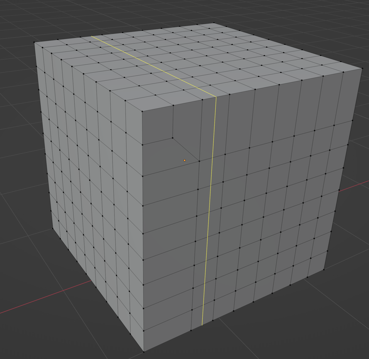
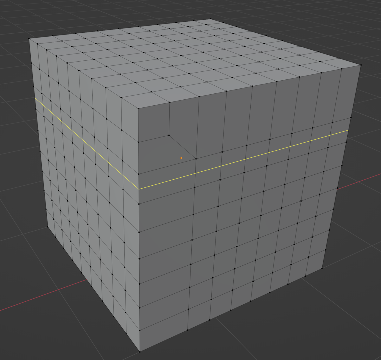
August 9, 2022 at 4:00 pm #75116Well, what we are interested in are 5 edge poles, those are the ones that have to do with changing directions. In your cube there, the one vertex you’re focusing on, that one just has 3 edges connected to it when it’s wrapped like a cube, those don’t do anything, the 3 edges one I mean. So this one:
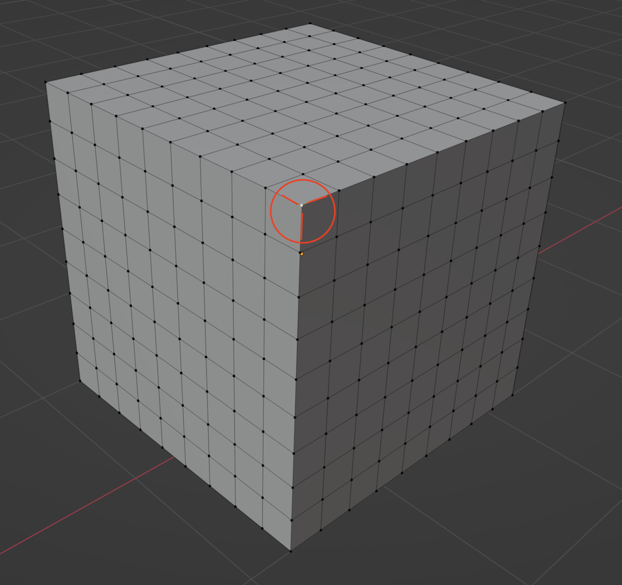
That is why you say it’s hard to see which direction is being changed, that’s because there is no direction being changed at all. The one that change directions are the 5 edges pole ones, and it’s nowhere to be seen.
So check this out, the one you have, lets break it down.
There are no poles changing any direction anywhere, because there are no 5 edges pole anywhere, as you can see if you break the visual spell of the cube just having its side bent.
Here the loop is going straight all the time. Even though you see it go down in a sense, there is no “turn” the loop takes when you see it continue “down” like that.
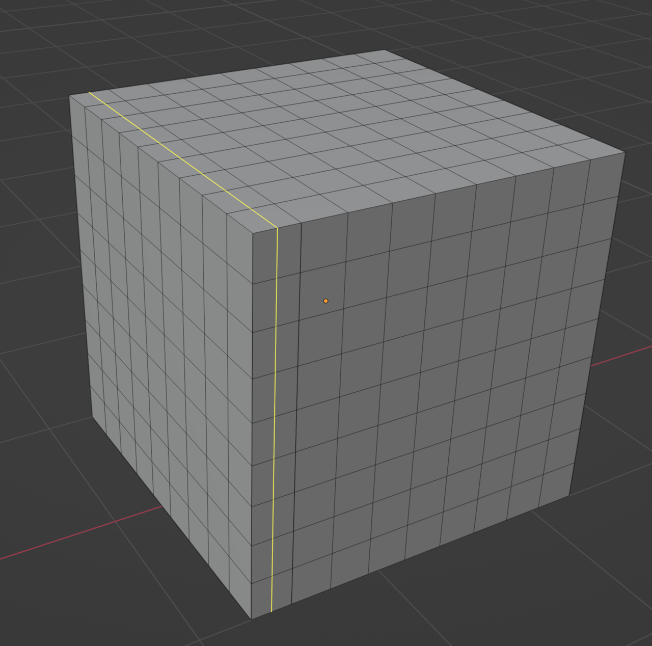
If we take that row of faces and we make it not bend down, you can see the loop is actually continuing straight in it’s path:
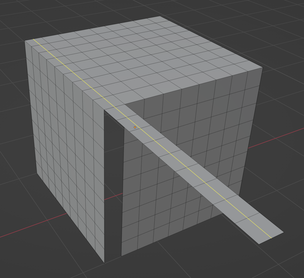
We can do this anywhere:
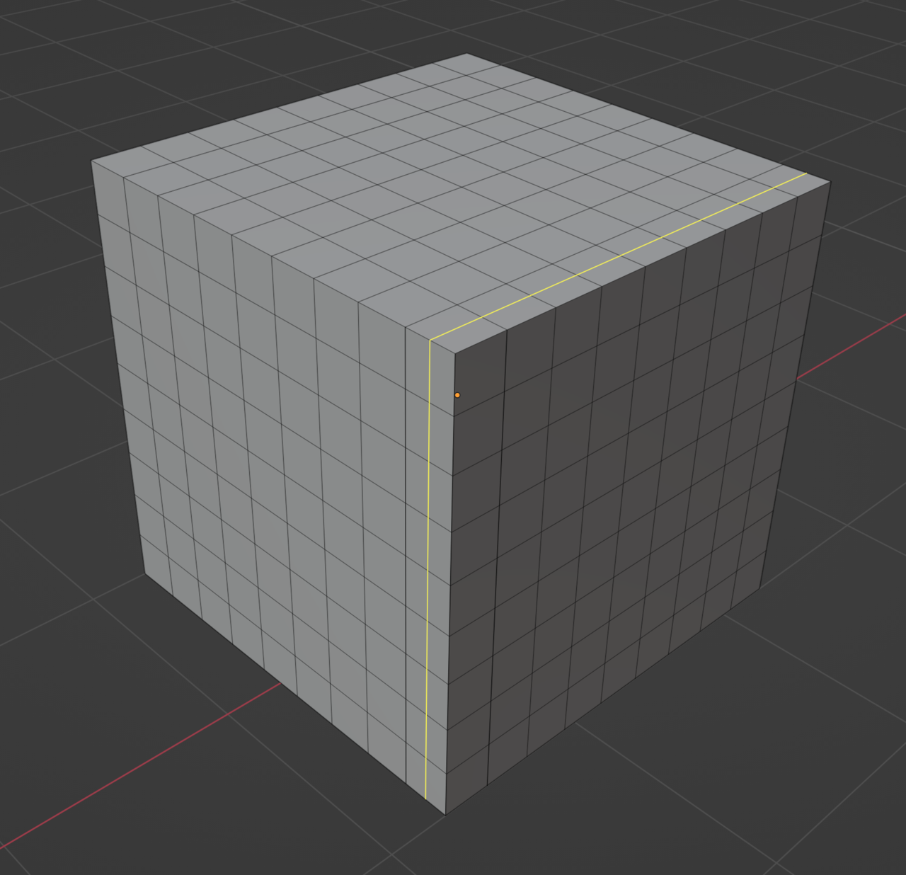
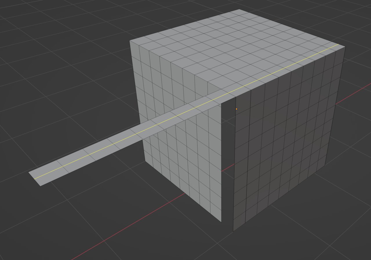
Even in this one that is not in a corner:
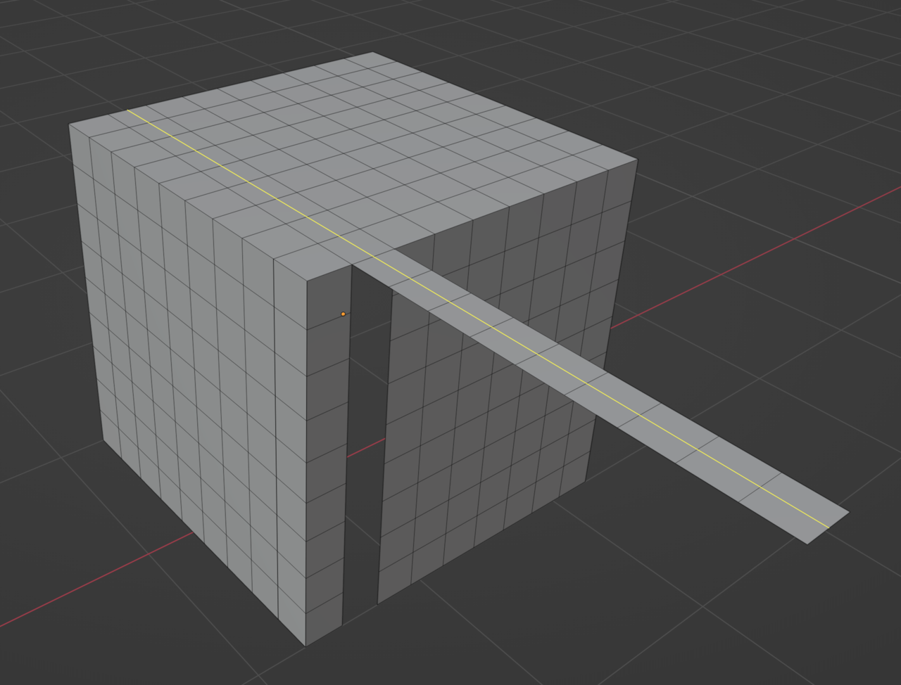
There is no 5 edges pole anywhere, the ones around have 4 edges that connect to the vertices so the loop goes on straight.
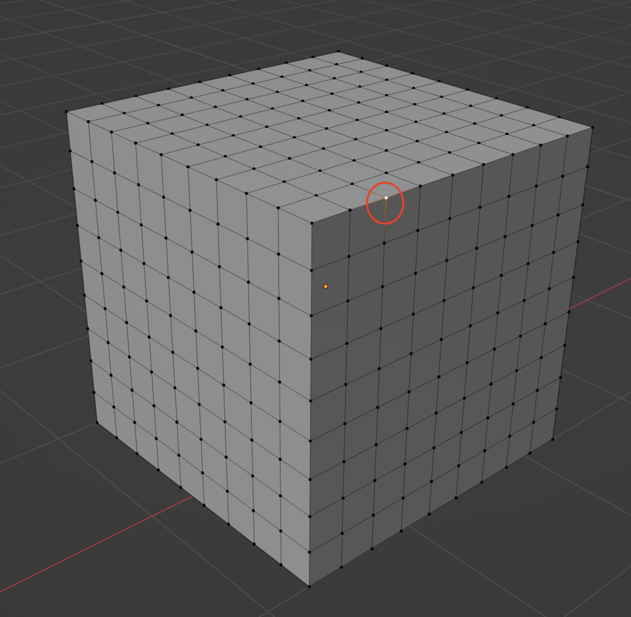
And yet see how when I put a 5 edges pole anywhere on the surface, now when the loop goes to that point, there is actually a turn on the way the loop was going:
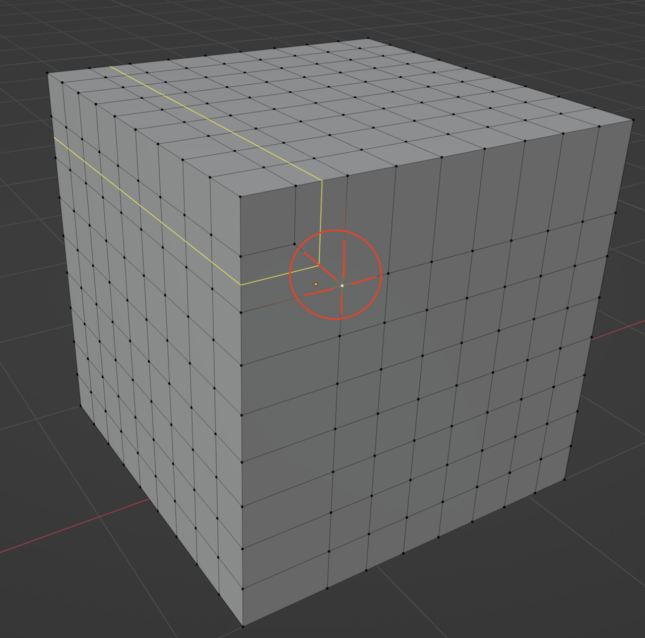
But anywhere else the loop doesn’t go through the 5 edges pole one, it goes on as normal:
 August 9, 2022 at 6:59 pm #75117
So Cristian, it’s all about control. Where do you want the loop to go? The whole pole changing direction thing you can see it everyday in real life if you pay attention. Let’s take a simple example in Blender first.
I want to control the edge loop so it makes a turn like this:
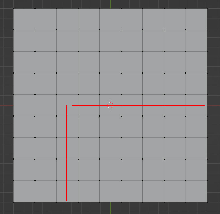
But right now if I hit Control + R and place my mouse there, the loop will just go on straight:
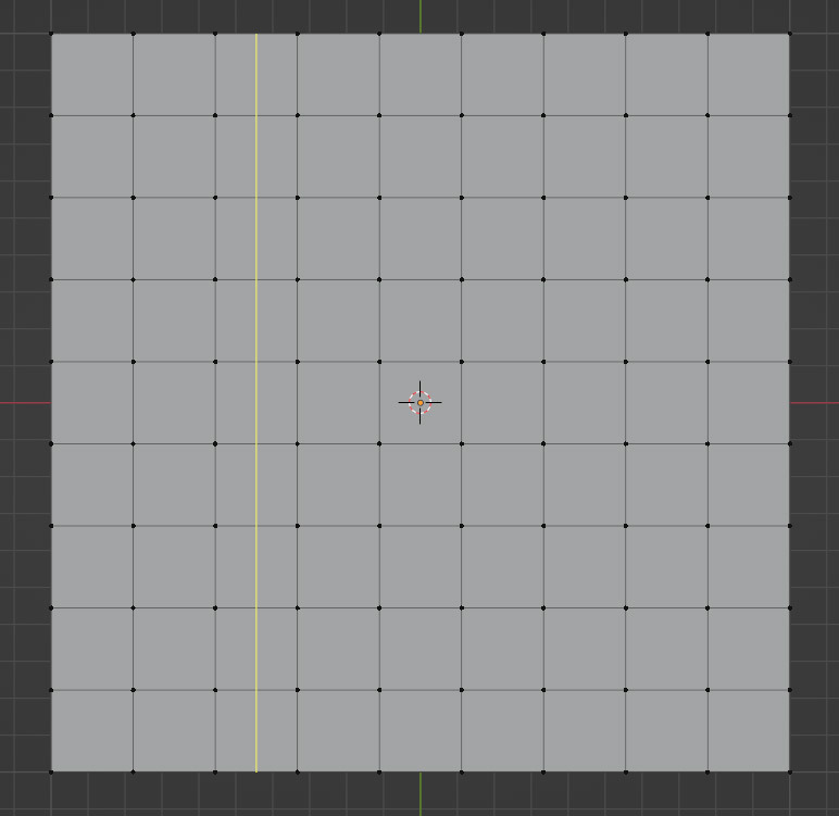
The answer is definitely not to bend the geometry down, that is not making the loop turn the way I want it, it’s just bending the geometry down.
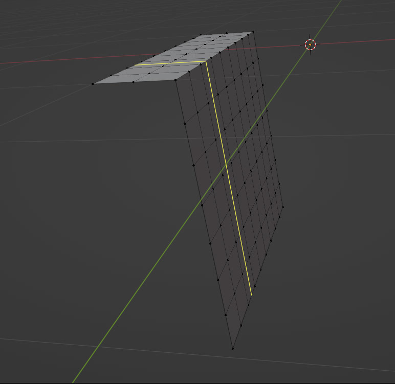
So I have to make this vert a 5 edge pole to achieve that turn
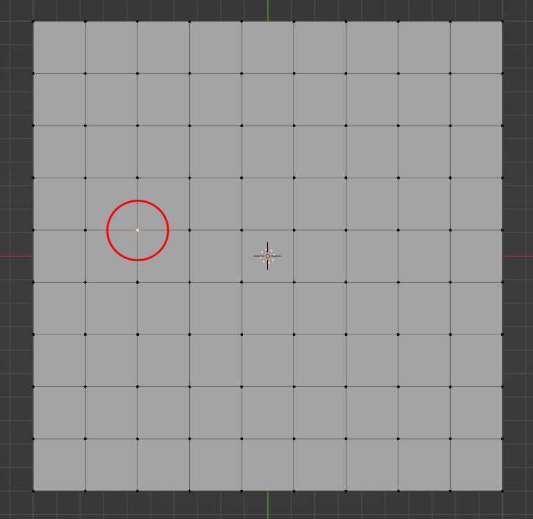
And here’s the result:
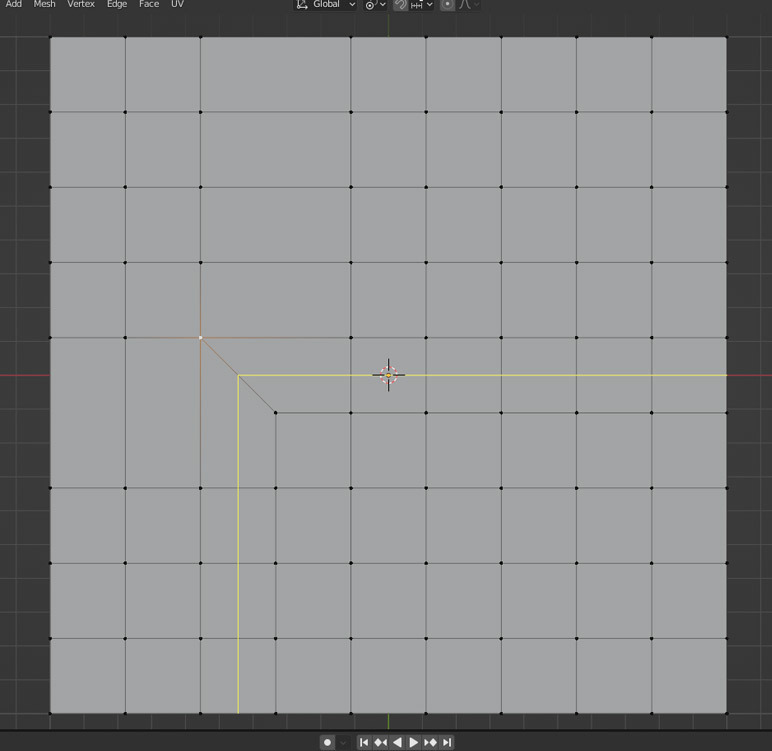
And see how that vert has 5 edges connected to it:
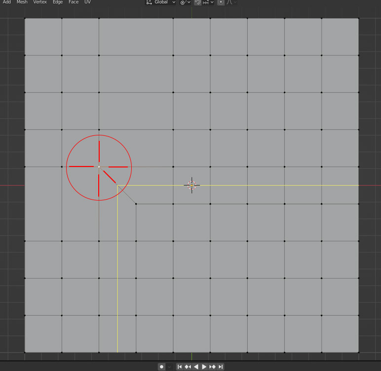
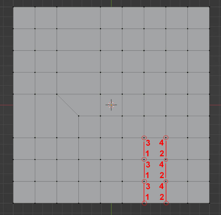
So a loop will go looking for a face and then the next face and then the next face and so on. So it’s 1, 2, 3 and 4 vertices, that’s a face, I’ll go to that one, then let me look for 1, 2, 3 and 4 vertices, that’s a face, I’ll go to that one, and so on again and again:
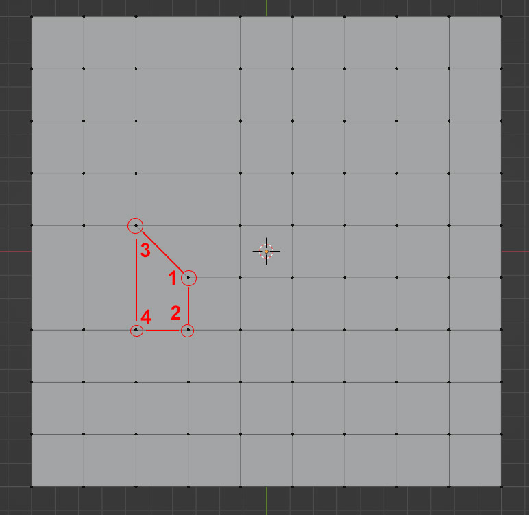
And when you turn a vert into a pole, so 5 edges connected to it, you can see what is it that happens to the face that makes the turn:

So it goes, 1, 2, 3, 4 and on to the next set of 1, 2, 3, 4
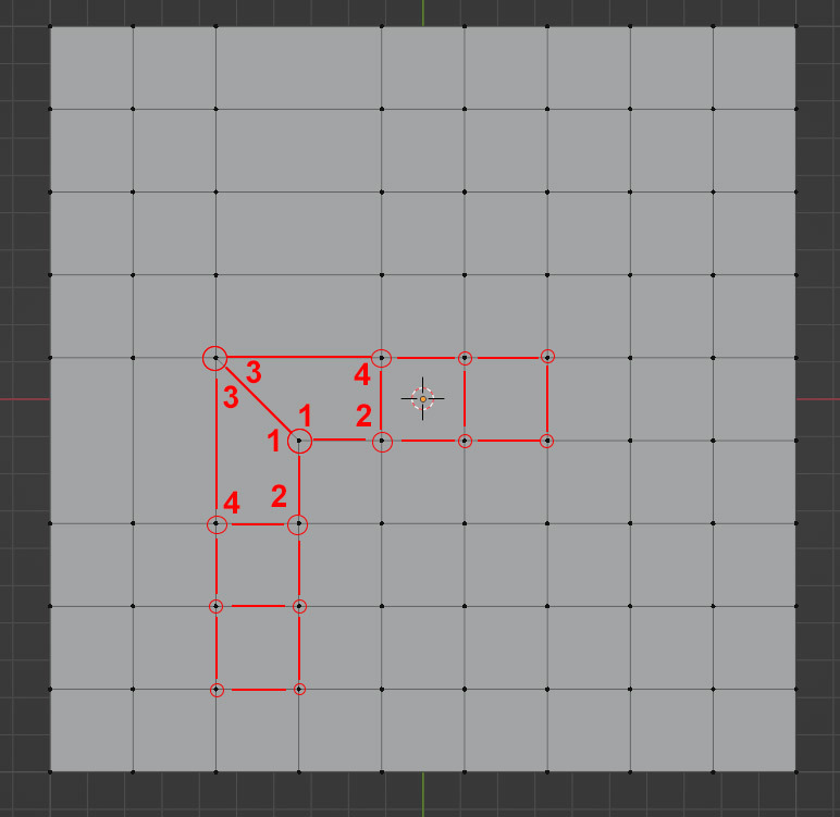
And you have that kinda L shape that makes the pole that makes the loop follow the new direction:
And it’s all because that 5th edge that grew, turning that vert into a 5 edge pole:
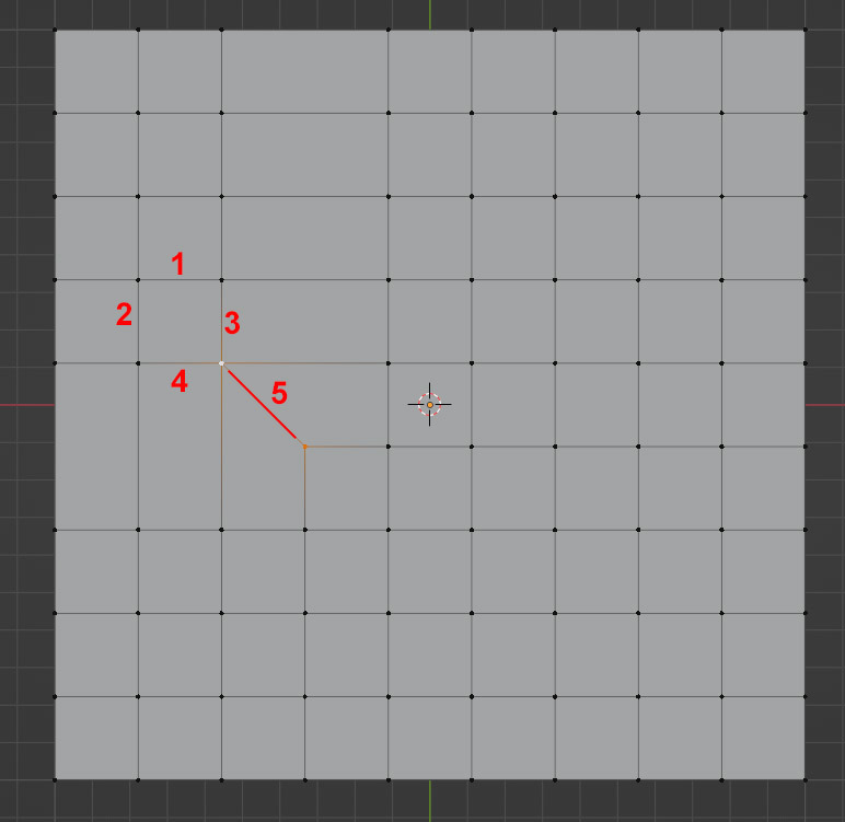
And that edge turned those two faces into that L shape. Both those faces share that 5th edge. That is the key part that makes the turn.
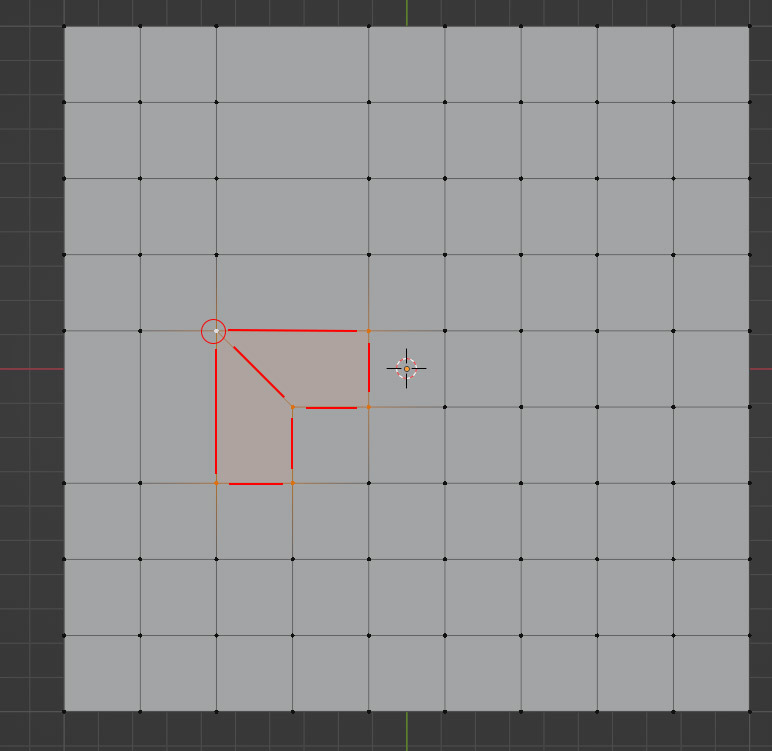 August 10, 2022 at 6:59 am #75118
In the image you shared, you can see the poles changing the direction of the loop:
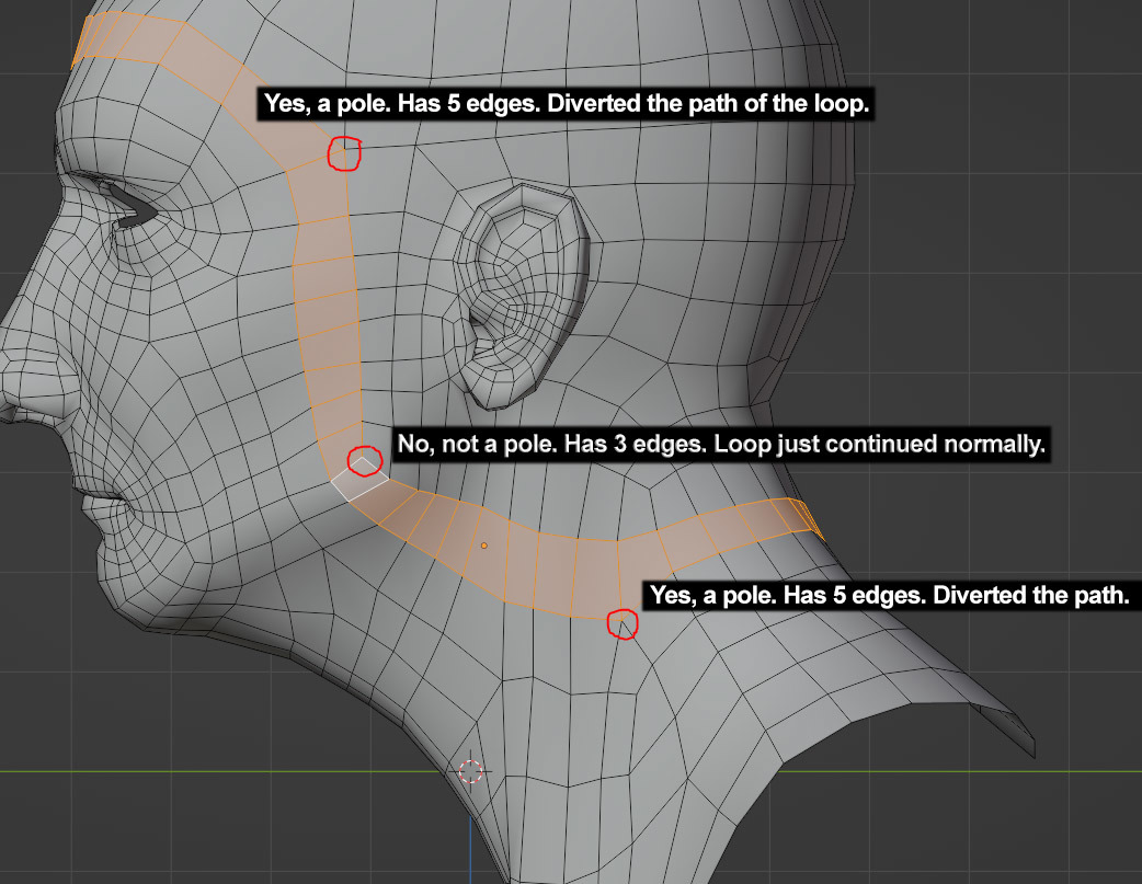
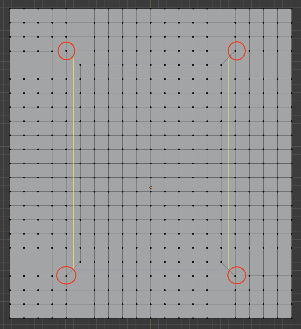
Out of the three red circles you used to highlight the vertices, the middle one, that only has three edges, since it visually looks like a turn, your brain would think it is turning, but it’s not. Remember, you see it that way because it looks like that with your eyes. From the perspective of the topology of a model, that is not a turn, it’s good old quad face after quad face that the loop takes directly.
See below how it just said ok, 1 vert, another vert, that’s 2 verts, another, that’s 3 and another, 4 verts, that’s a face, I’ll go there. And then again with the next 4 sets of verts that made that face. If you count the edges that make up those faces, they all have 3 to 4 edges connected to the vert.
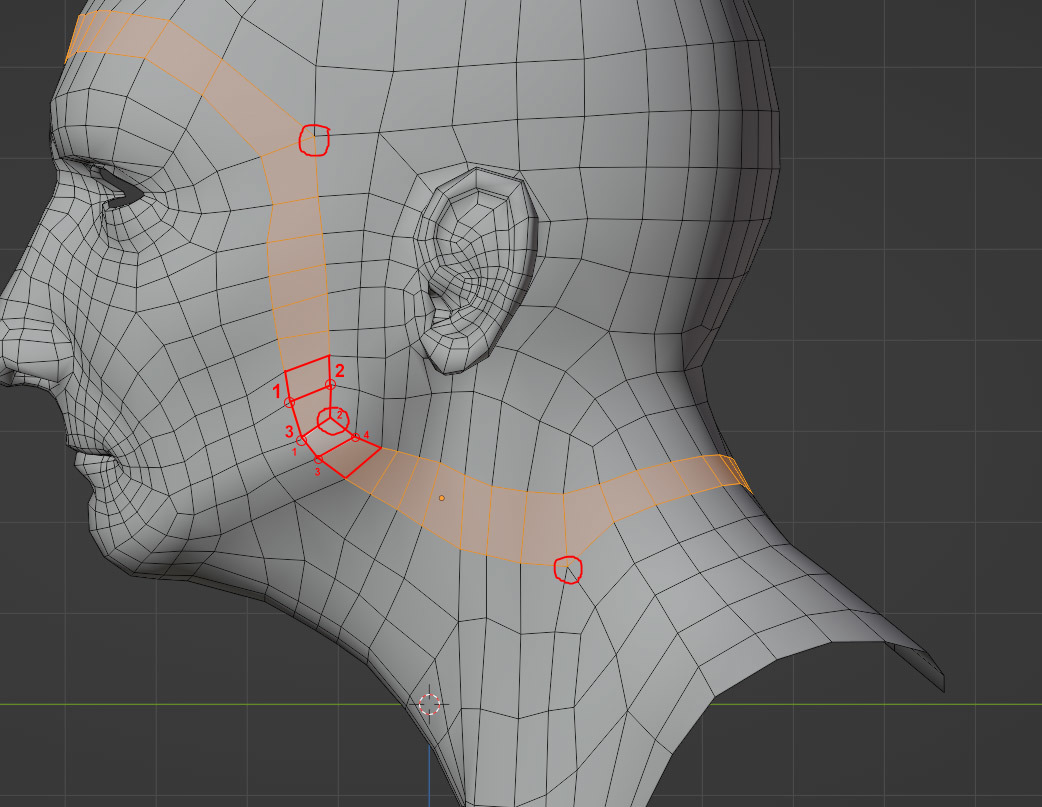
Even though you can arrange the faces to visually look like a turn, it is not. Remember here, see how it turns and turns, but the loop of just going from one quad face to another, with vertices that have 3 or 4 edges connected to them.
The difference comes when a vert has 5 edges, and that vert becomes a pole.
See how that path could’ve gone like this if there was no pole there. With a little bit of Photoshop we can get the idea across. See how the loop would have just continued in it’s normal path without the pole. 1, 2, 3and 4 verts, a face, I go there, then 1, 2, 3, 4 a face, the loop continues to that face.
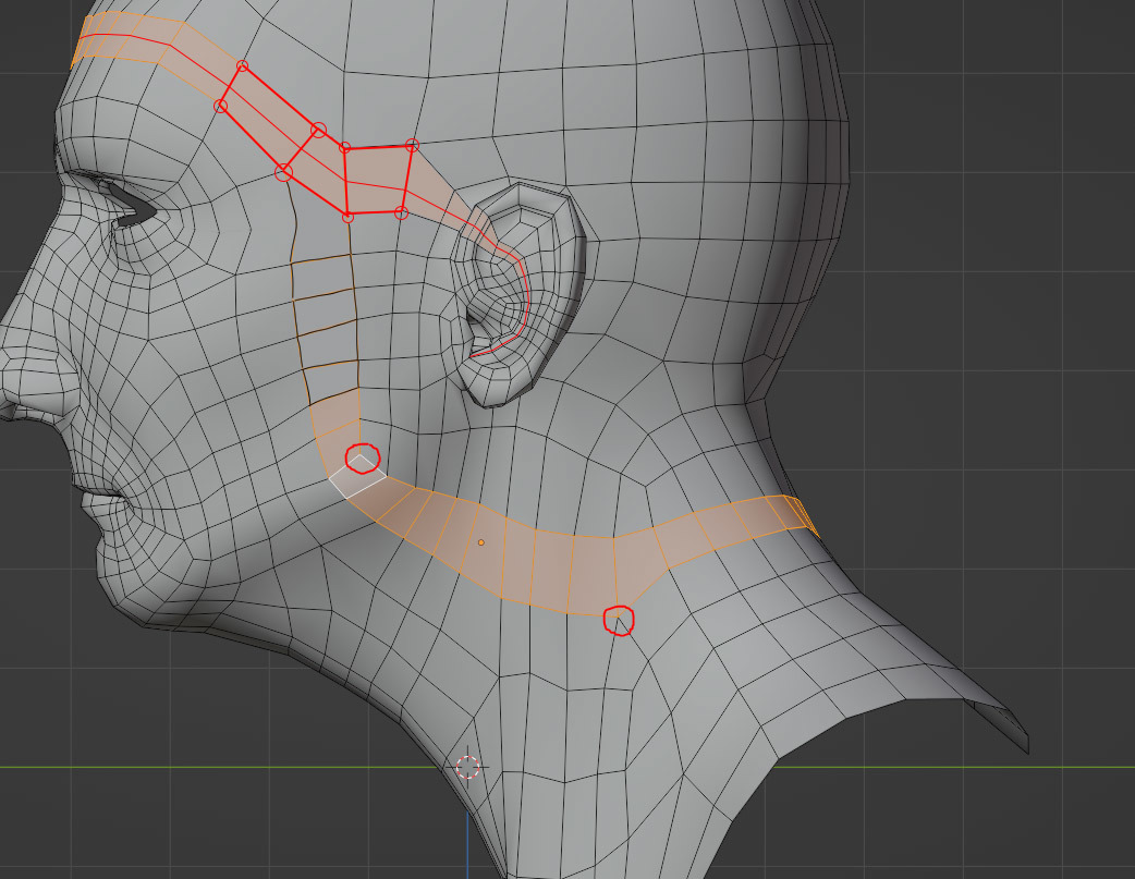
But what if you didn’t want the loop to go in that direction, what if you wanted to control it and take a turn and go down, that’s when you change your mesh with a pole there so it turns in the direction you want it to go. And that’s what you have there.
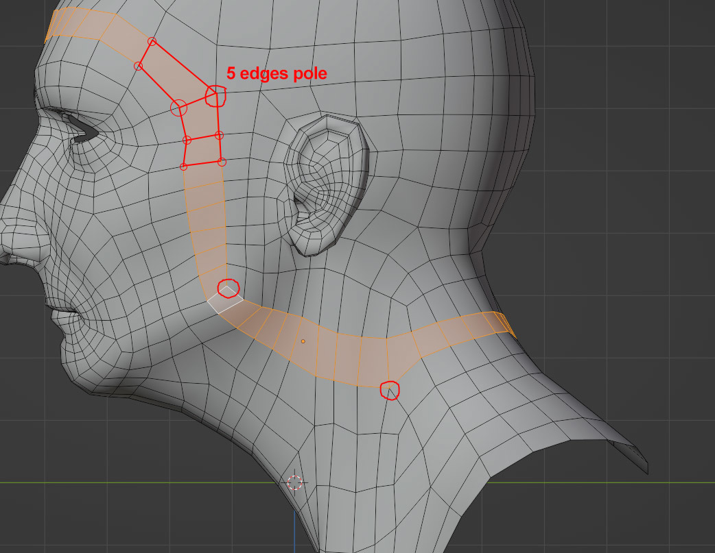
I know it’s not easy to see, but you’re brain will get used to it if you practice it yourself. Add a plane and subdivide it and try changing the direction of the loop to where you want it to go. You’ll see how you’ll use the pole intuitively after a while to change the directions and make turns in your geometry.
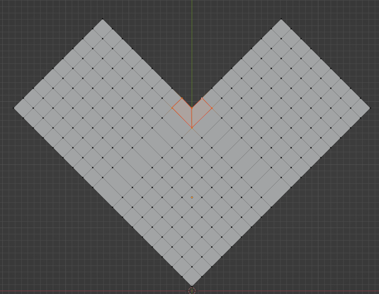
August 10, 2022 at 8:39 am #75119In this example, that vertex is not a pole, it has 4 edges connected to it.That is why when you select the face loop, it goes straight all the way down.
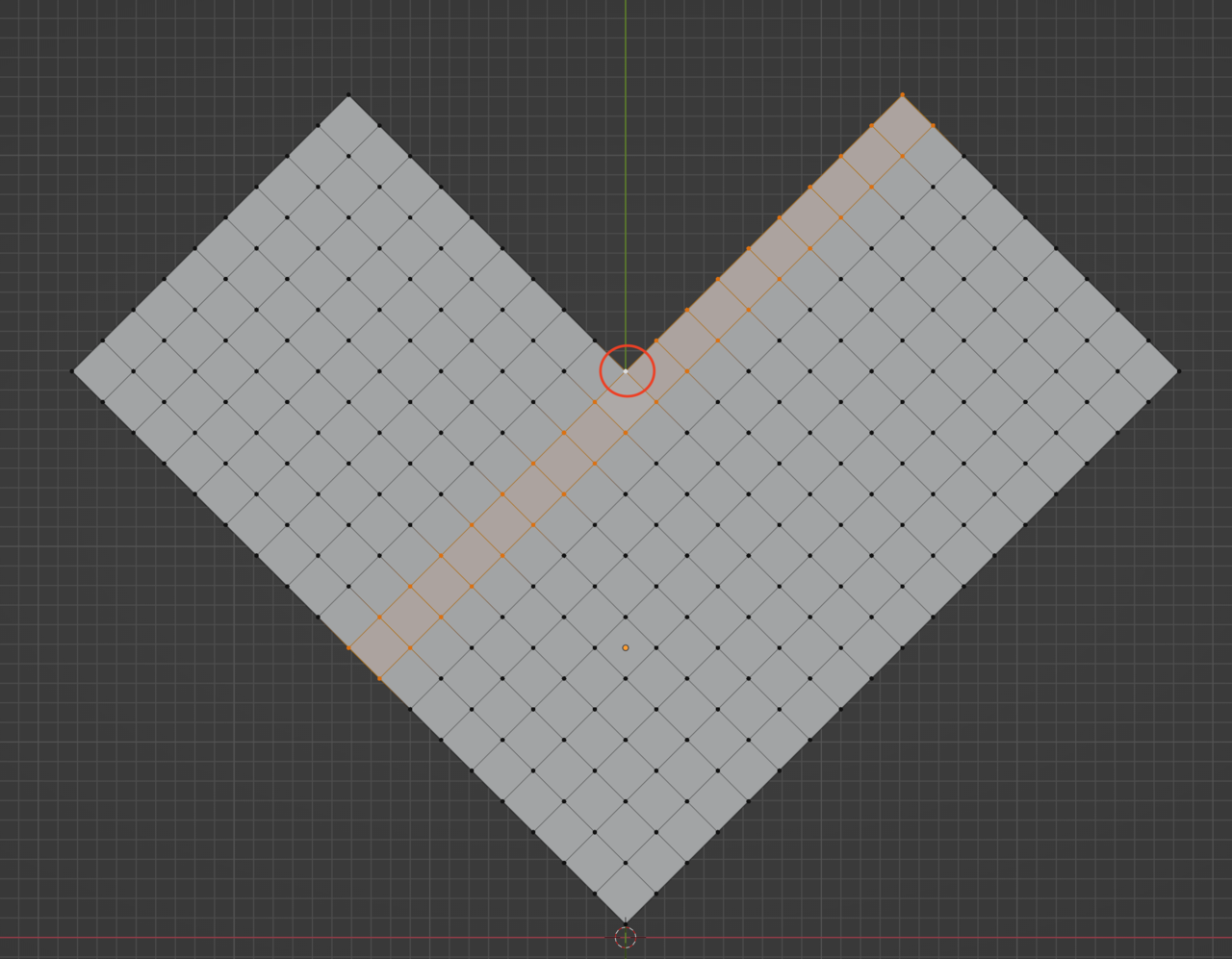
See the 4 vertices that make a face one after the other:
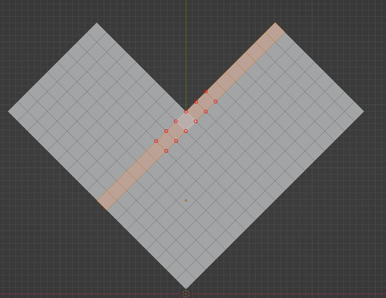
Now say you want it to make this shape instead. You’d have to make the loop turn in that direction.
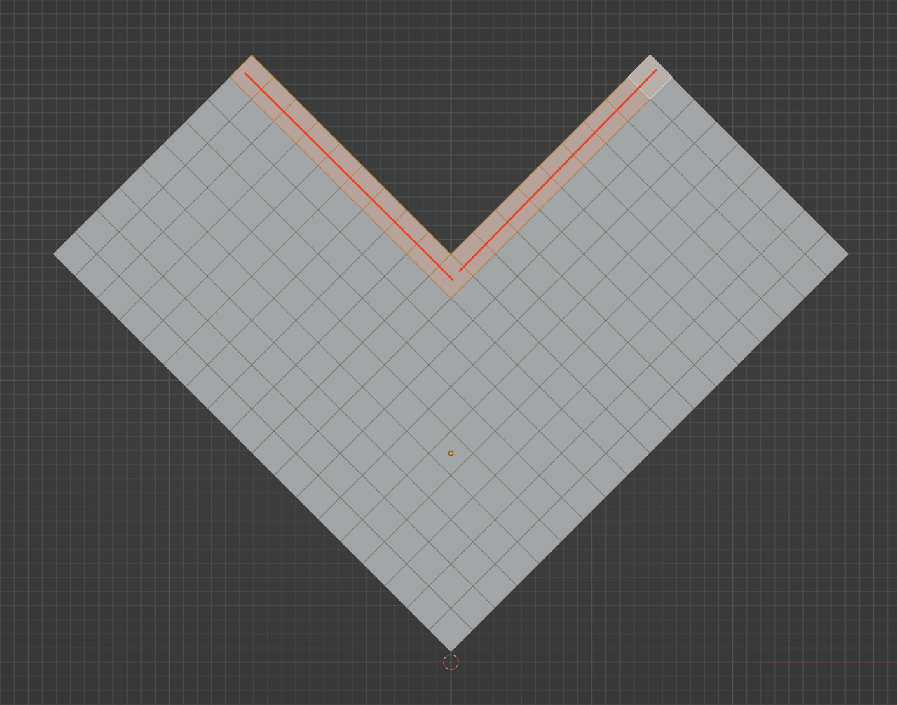
So you need to make this vert a pole.

You start by making that fifth edge here:
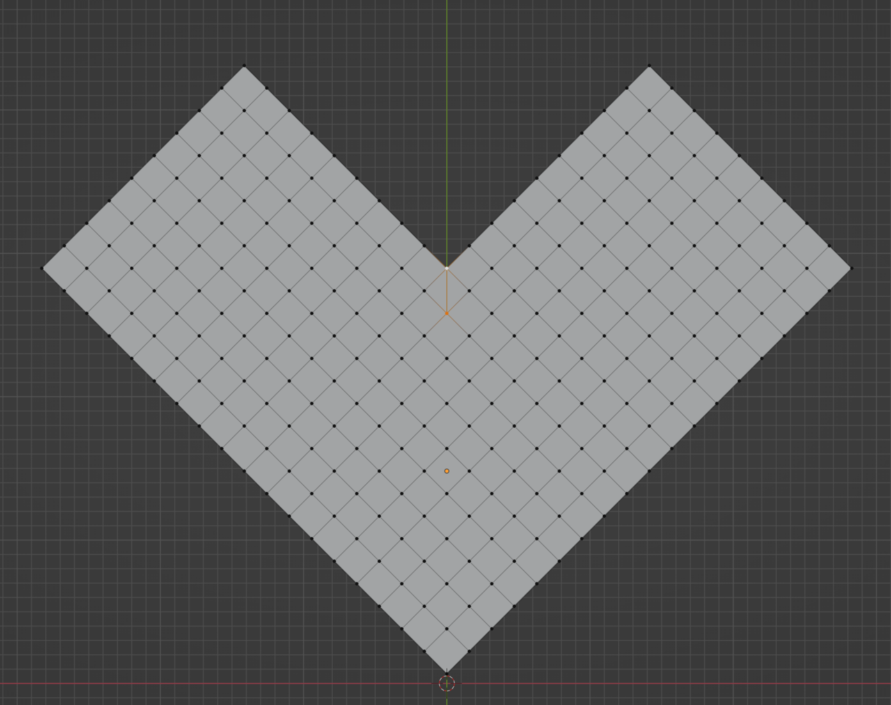
But now you have two triangles on that face, so you take this vertex and slide it to meet with the other, the pole one:
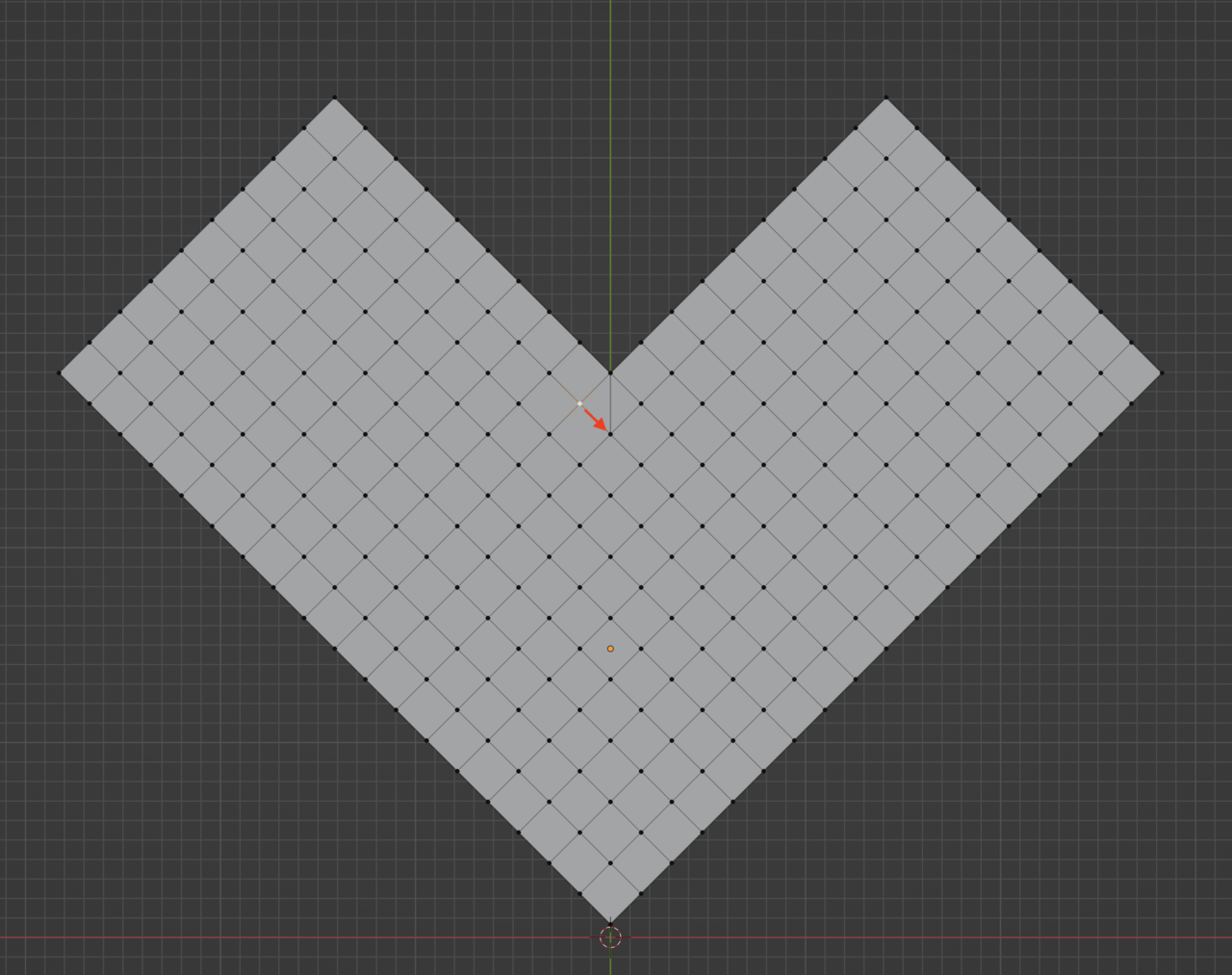
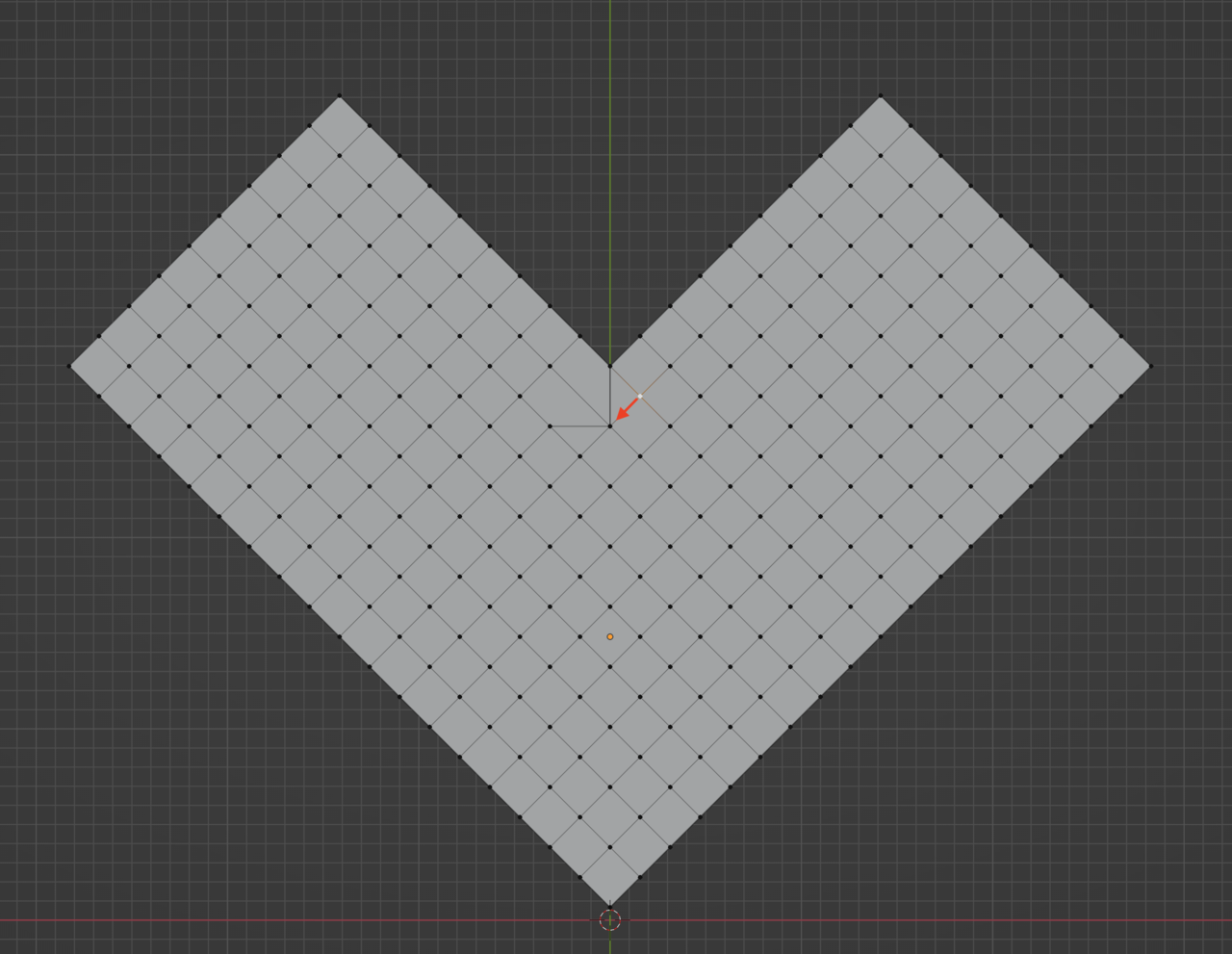
Do the same with the other one, slide it towards the pole:
Now merge them by distance, because you have 3 verts one on top of the other there:
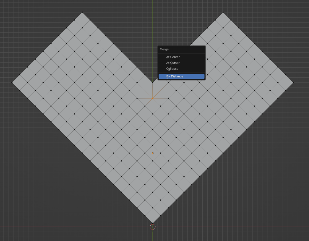
So you got rid of the two triangles now by sliding those vertices. But now you have a vertex that has 7 edges connected to it and that’s a big no no. So you delete the two loops that are causing that problem. This one:
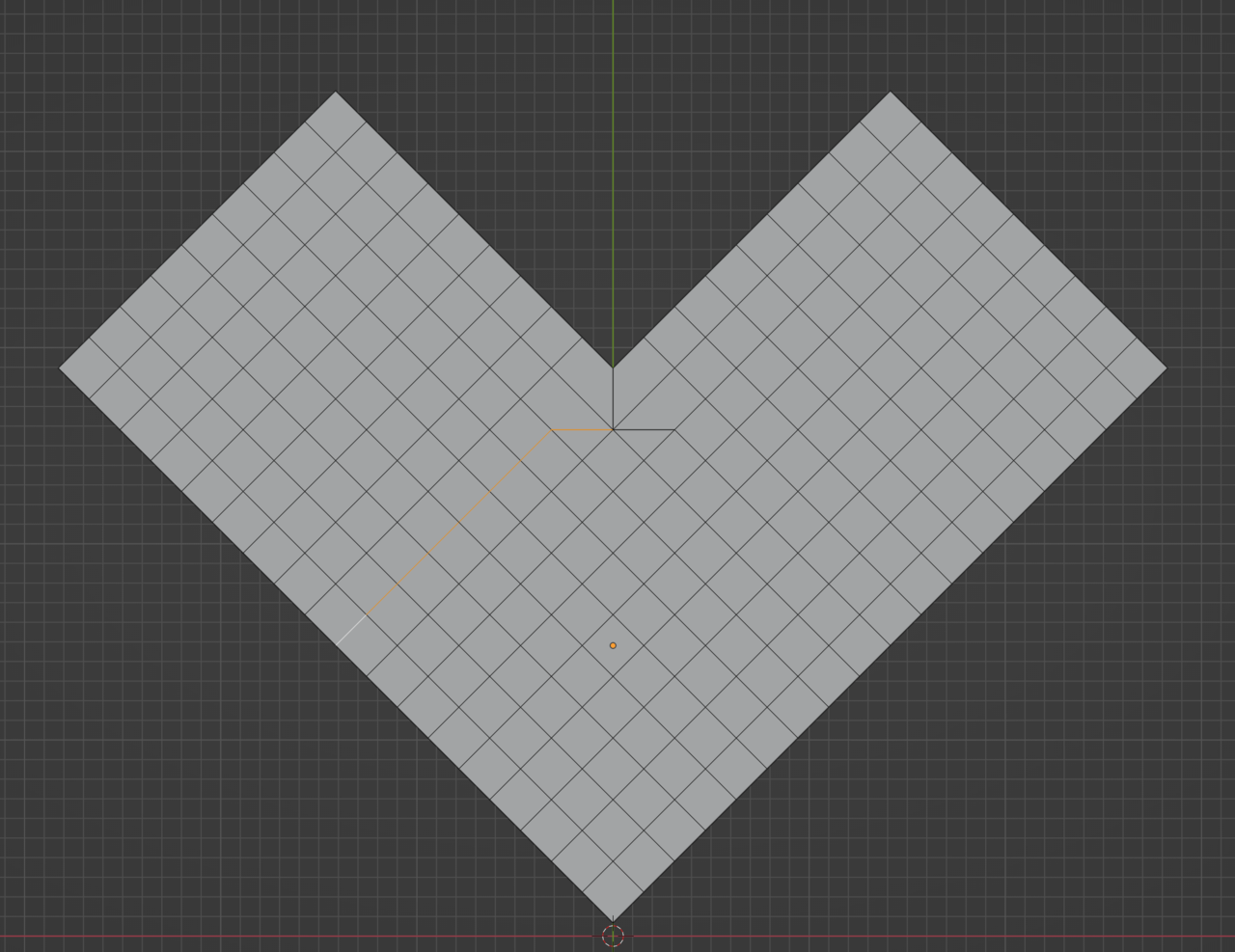
And this other one:
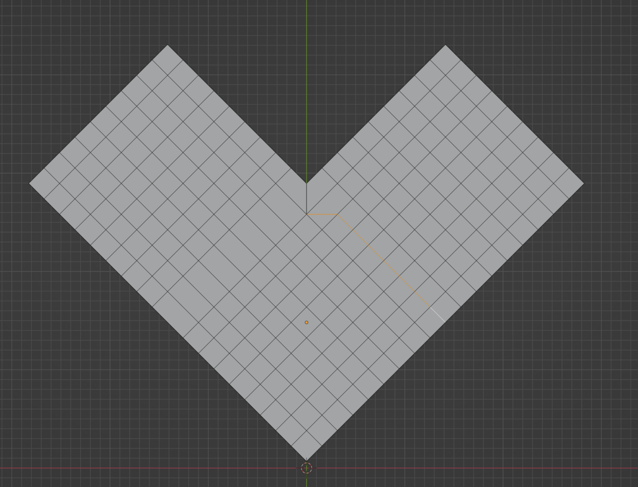
And now the loops turns the way you want it to go:
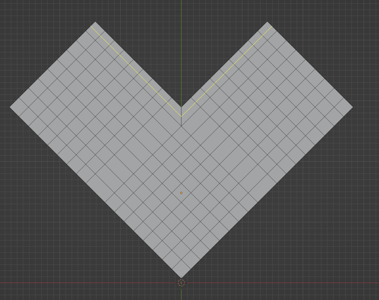
Because we made that pole there with the 5 edges:
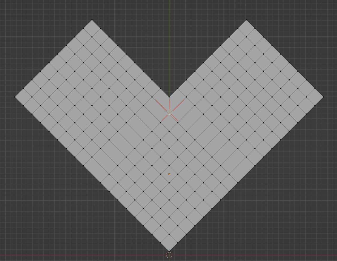
See that L shape we end up with:
-
AuthorPosts


- The topic ‘Loops changing direction without poles’ is closed to new replies.