
Is this hard surface geometry ok?
Forum Archive › Is this hard surface geometry ok?
- This topic has 48 replies, 5 voices, and was last updated 8 years, 3 months ago by
Will.
-
AuthorPosts
-
April 3, 2018 at 6:44 pm #9614
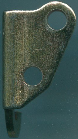
I am trying to model this little metal clip:
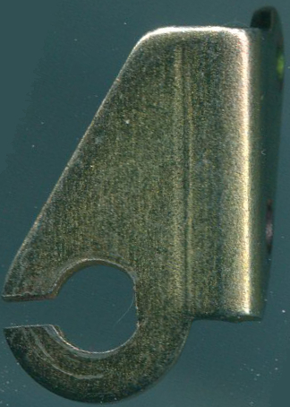
And I want to know if this is a reasonable outline geometry for this face, given that the ring part can (with a little bit of force) be deformed.
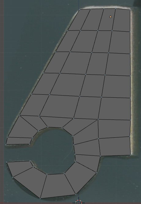
Thanks for any input! I’ve attached the .blend for it at this stage in case it makes it easier to show where I am messing up.
April 3, 2018 at 7:25 pm #34828Note I don’t mean for final geometry, just wondering about the basic idea of a single edge loop around the ring and how it connects to the rest of the geometry.
April 3, 2018 at 8:03 pm #34829Looks fine to me.
Just keep in mind that if you want to solidify it (give the metal piece a thickness) there will be some stretching and compression going on if you deform the ring part.
Other than that, the second to last vertex on the right edge is not aligned with the rest, but should be, according to the ref image.
April 3, 2018 at 9:55 pm #34830Thanks for the reply 🙂
Is there a way to mitigate non-natural stretching and compression (obviously the real metal will have issues too if pushed too far) by strategically placed high- or low- geometry areas or edge loops? I’ve noticed in modeling faces many people put 2 rings around the eyes, would that be any benefit here?
April 3, 2018 at 10:04 pm #34831The way I would approach it is by simply deforming the ring the way you want it and then work on the problem areas.
I did not spend too much time with that, but I would say that the double loops around the eyes are for that purpose, indeed. Doesn’t mess up the geometry too much when you want to animate the eyes since the resting eye structure is still present.
If you add more loops around the parts that you want to deform, it will give you a smoother result, but depending on the deformation degree it might still cause you issues that are now a bit more difficult to get an overview of, since you now have to deal with more vertices and faces.
I would recommend just solidifying that metal piece as it is in the screenshot, then deform the ring and see where the issues actually appear. From there you can still work those areas, add more loops etc.
April 3, 2018 at 10:16 pm #34832Your reference shows a vertical line, you should find it back in your topology. I believe the piece is bent a bit at that line.
You have to use a subdivision modifier as quick as possible. If you use it now you will find out that all the effort to align the vertices with the background image has been in vain.
You can align vertices by selecting them and press : ‘s + (axis) + 0 + Enter’. For the example in the image : s + x + 0 + Enter. (Scale zero at the X-axis)
The edge loop for the inner ring will work just fine but not for the outside. No problem use a different way.
If you post a file you have to pack all the external files into the blend file. The background image is missing. (File/External Data/Automatically Pack Into .blend.)
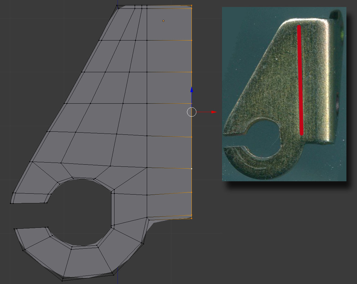 April 3, 2018 at 10:28 pm #34833
Here’s your file back.
 April 3, 2018 at 10:40 pm #34834
I’m going to be honest, I don’t think it’s necessary to work with a Subdivision Modifier at all in this case.
The entire thing can be done with Smooth Shading and Beveling reducing the Polycount drastically without messing up the original mesh.
April 3, 2018 at 11:17 pm #34835Hi thanks Delores, that line is actually just a mark on the metal from usage, not actual different geometry. Thanks very much for taking the time to make a modified version and for your input :heart:
I’m mostly wondering about the general concept of having a ring around the C-shaped hole like this and if this is a normal, professional approach to how to model a shape like this rather than the details of matching it to the reference. This question gets even more important as I get around to the side of the clamp which has two screw holes.
Currently I have it like this:
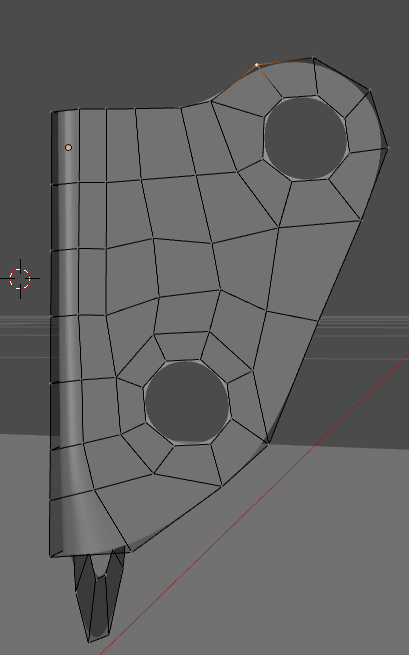
but I think I know enough to know that something is fishy about this topology. I see a 5 point pole and things just look kind of “off” but I don’t know enough to know what the correct topology _should_ look like in this case. Here is now the piece looks from the side:
Having it in object mode and everything smoothed out looks good enough:
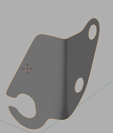
but like I said, i’m worried about this ugly-to-me looking topology that I have going on here and how to know how to model this correctly.
One thing I tried doing is using Smooth Vertex on the side with the 2 holes to hopefully clean up the positions of the vertexes a bit, but it shrinks the whole model too. I _do_ think there is a way to constrain the outside vertexes and smooth the shape of the inside ones, but I couldn’t figure out how to do that.
April 3, 2018 at 11:25 pm #34836AFAIK subsurf is kind of needed because of the screw holes on the side, unless there is a good way to get them round without it that I don’t know of.
Note: I’m not too worried about poly count necessarily, just worried about best practices for a general-purpose model that might be used for a variety of purposes.
April 3, 2018 at 11:51 pm #34837Cool modeling girl 🙂
I wouldn’t worry to much about good looking topology for the moment. You will automatically get better at it the more you do it. The most imported for now is that you manage to make the shape as the reference. You can use the smooth tool in the specials menu if you do not select the outside vertices and make those looking good manually.
You are right, that vertical line is not a bent, now I see the other side too. These are the marks of the ‘V’ press the object was bent into. I found an image on the net for your information how stuff works.
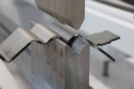 April 4, 2018 at 12:08 am #34838
That’s a really cool photo and great info on how the piece is manufactured!! I didn’t even think about just not selecting the outside vertices when doing the smoothing, that totally makes sense and does help:
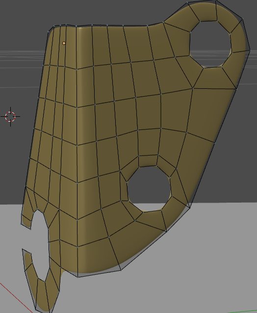
I’m curious if these places are ok, like not in a practice learning model, would they be ok in a production model:
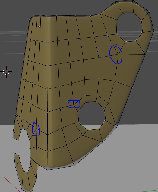
and about the concept of making rings around the holes, is that the common practice? what changes are needed to make the topology appropriate for a real-world production model?
April 4, 2018 at 12:59 am #34839A real-world production model isn’t made with Blender Catherine, but cad/cam. Cad/cam does not work with topology but with technical drawings. It means front/top/side views. Cad/cam makes those views into a 3D model. This file is given to whatever machine that will make the object. I’m afraid you’re at the wrong forum for this.
The best case scenario for Blender is that you can have it 3D printed.
In every object you model you will have poles like that, there is no way around it and there is nothing wrong with it either.
I have made many drawings for a laser machine in my life.
This is a way your object can be made :
- First you make the drawing of the flat plate with the shape and the holes.
- You tell the computer how many pieces you need.
- The computers calculates the position of all those pieces on a standard steel plate for example : 2 m x 1 m.
- This information is given to a computer guided laser machine.
- This machine takes the needed plate out of the supply and starts cutting all the pieces.
- Those lasered pieces go to somebody who grinds the edges smooth.
- After that, those pieces are given to the bender who bends the flat object into his ‘V’ press into an angle of 90°
- When all is done the thing is galvanized.
Looking at the edges of the piece in your reference, I don’t this your object is lasered but pressed-out and then bent.
April 4, 2018 at 1:41 am #34840Oh I’m sorry I didn’t mean production as in actually producing metal pieces. I mean as in using the model in more than trivial learning use cases. For example, using it as part of a product model where the item can be virtually disassembled in a 3D space.
or another way to say what I mean is what changes to the current topology are needed to get a professional-looking topology.
April 4, 2018 at 1:45 am #34841You already have a professional looking topology. I’ve seen worse on this forum.
-
AuthorPosts


- The topic ‘Is this hard surface geometry ok?’ is closed to new replies.