
Darius’s Blender progress
Forum Archive › Darius’s Blender progress
- This topic has 140 replies, 13 voices, and was last updated 5 years, 7 months ago by
dariusjohnson.
-
AuthorPosts
-
September 18, 2020 at 1:09 pm #59787
Hi Darius, I feel your frustration on this…Here’s a few tips for you that might help. Go into your preferences and make a few changes.
Settings:
Under Memory & Limits I would up the number of undo steps…unless your perfect and never make mistakes….(mines set at 200 and thank God for the ability to save progressive versions of the project I’m working on or I’d be… )
Undo Memory Limit: 0
In Save & Load tab:
Under Blend Files / Save Versions: at least have 1 and save progressive versions of you file as you work.
Make sure Auto Save is checked and how often you want it to save. (save the file yourself before this will really benefit you.) I’ve set my timer at 1 because some files are super heavy and my blender has crashed more with 2.8 and 9.
September 18, 2020 at 1:10 pm #59788Those look awesome 💓
September 19, 2020 at 1:48 am #59789Thank you, I didn’t know you could increase the number of possible Undos. This will help me.
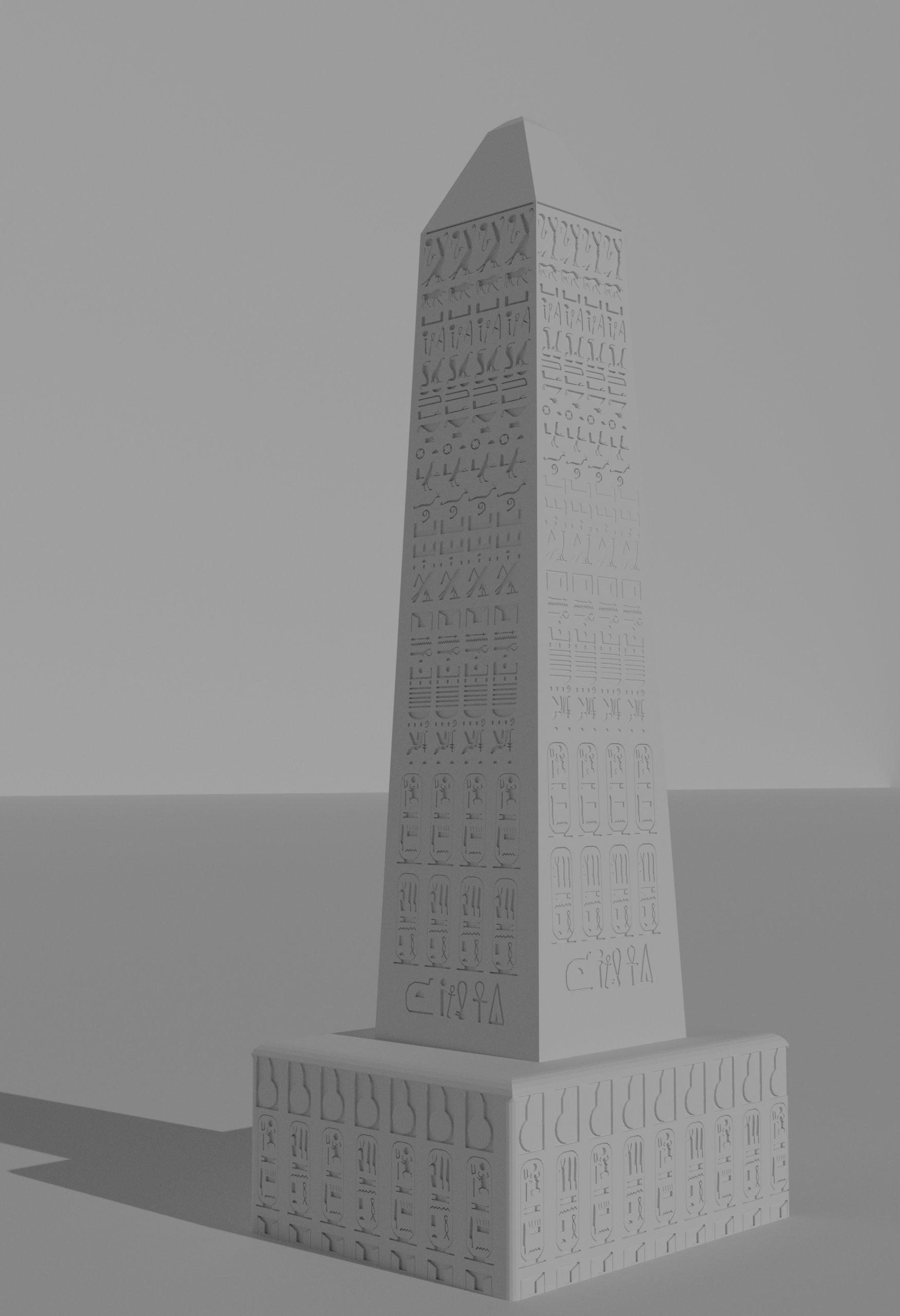
September 19, 2020 at 11:45 am #59790An ancient Egyptian Obelisk built by Sety II.
 September 19, 2020 at 12:42 pm #59791
I like it, but that middle tread loooks very unrealistic to me. tread needs to overall be pretty level. Otherwise horrible road noise. Also lack of traction.
September 19, 2020 at 2:18 pm #59792Great 👍! The virtual ancient Egyptian world gets more and more “populated” 😀.
September 19, 2020 at 2:20 pm #59793At which location is/was this obelisk standing?
September 19, 2020 at 11:43 pm #59794At the entrance of Karnak Temple in Luxor, On the right
September 20, 2020 at 2:24 am #59795September 20, 2020 at 4:46 am #59796In the First computer animation at the beginning, it is one of the first two obelisks. The left one was destroyed with time, the one at the right is the one I did. I took the references from this.
September 20, 2020 at 10:21 am #59797Obelisk Fragments.
 September 22, 2020 at 11:19 am #59798
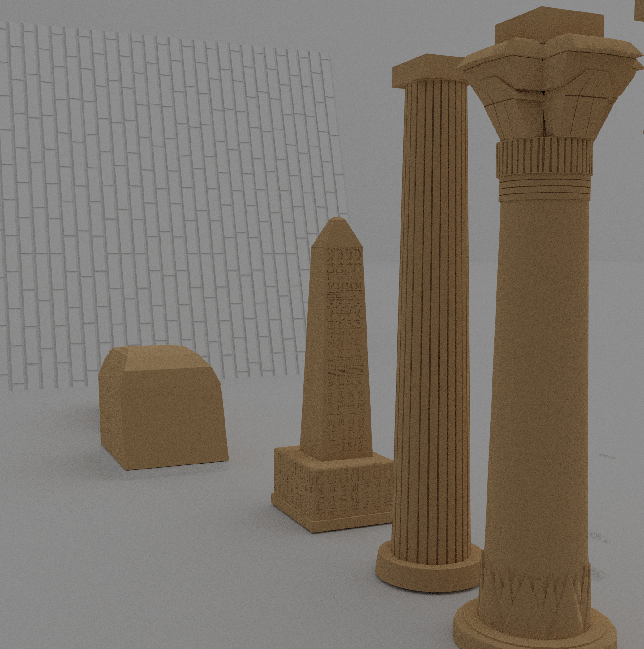
I tried to play around with material and procedural texture a little bit. I used the noise texture to simulate some kind of dirt on the surface of the objects. What baffles me is the brick texture which is stretched along the surface of the face. I know this is a common problem, but I didn’t do well-thought research, I just wanted to share this image and ask for a direction to follow concerning the learning of texturing and material (I am halfway through the fundamentals of materials course but the course doesn’t seem to cover texture).
 September 22, 2020 at 11:30 am #59799
Nice color for the columns 😀. You maybe need to apply a scaling of your objects.
September 23, 2020 at 1:00 am #59800I tried it but it didn-t work
September 23, 2020 at 5:07 am #59801Okay, I’ve tried it myself and get this with the default settings:
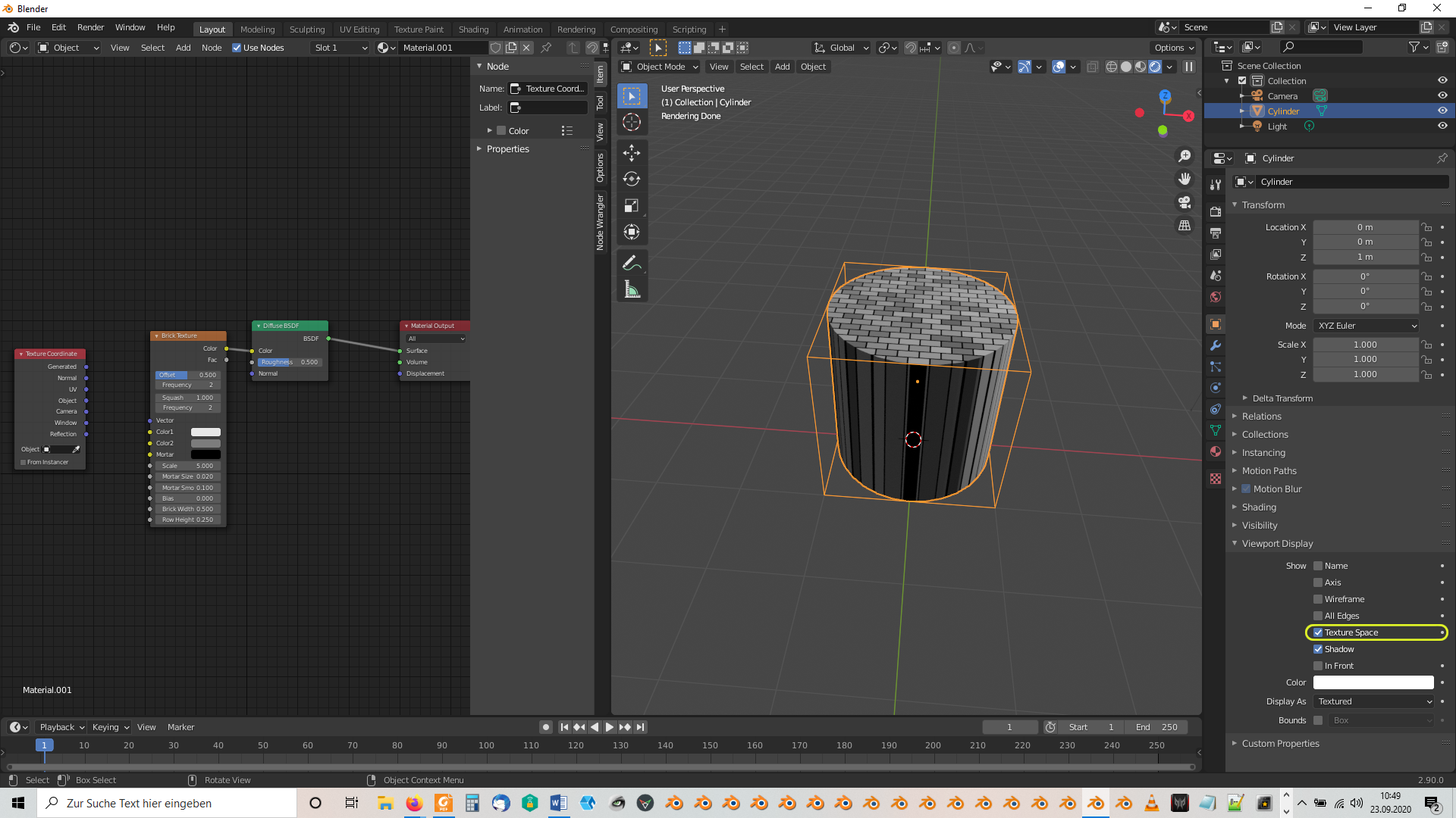
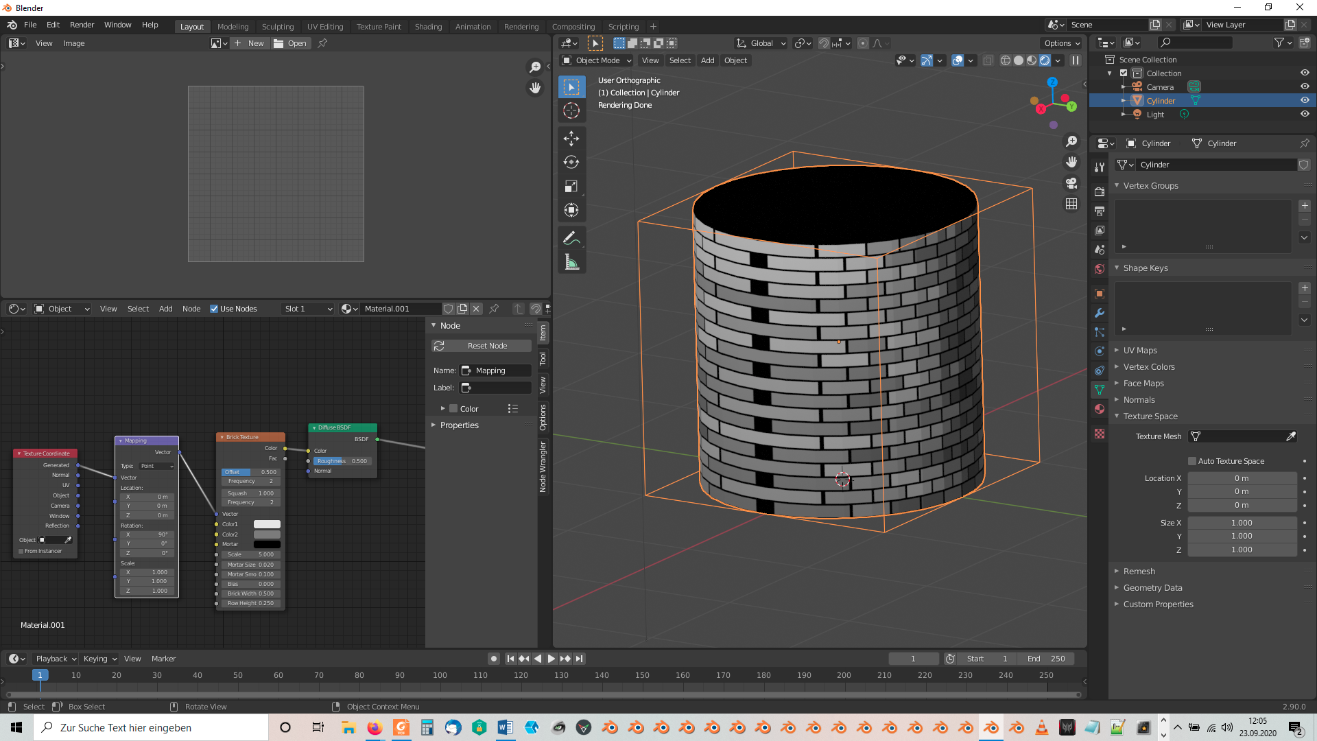
Procedural textures use “Generated” texture coordinates per default as you can see with the unconnected “Vector” input socket of the “Brick Texture” node in the image above. Therefore connecting the “Generated” output socket of a “Texture Coordinate” node doesn’t change anything:
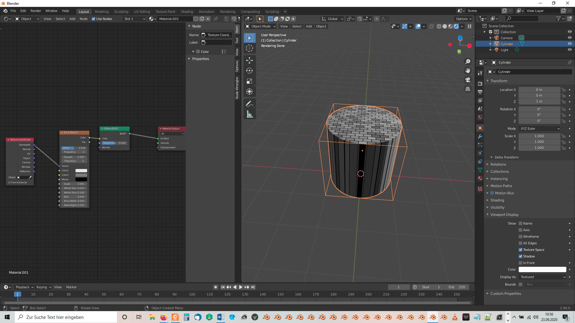
This “Generated” texture coordinates refer to the so called “Texture Space” which can be made visible as a box around your object by checking the box with that label in the “Viewport Display” panel of the “Object” tab of the “Properties Editor” (yellow frame in the first image above. The texture coordinate system origin is in the lower left corner of that box if seen from the front (press Shift + 1 with your object selected in “Object Mode” to get the front view of the “Local Texture Coordinates System” of your object). This “Texture Space” box is often confused with the “Bounding Box” of an object which can be made visible by checking the “Bounds” box at the bottom of the same “Viewport Display” panel. The confusion happens because both boxes have the same location, the same dimensions and the some orientation as long as you don’t move or scale the “Texture Space” box directly. The “Texture Space Box” is just a visualization for the “Texture Space” which extends infinitively in all directions from the origin in the lower left corner of that box. The upper right corner of this box has the coordinates (1,1,1)
The stretching happens because the “Brick Texture” is projected upwards from the bottom of the “Texture Space Box”. If you connect the “UV” output socket of your “Texture Coordinate” node with “Vector” input socket of your “Brick Texture” node, then you get this:
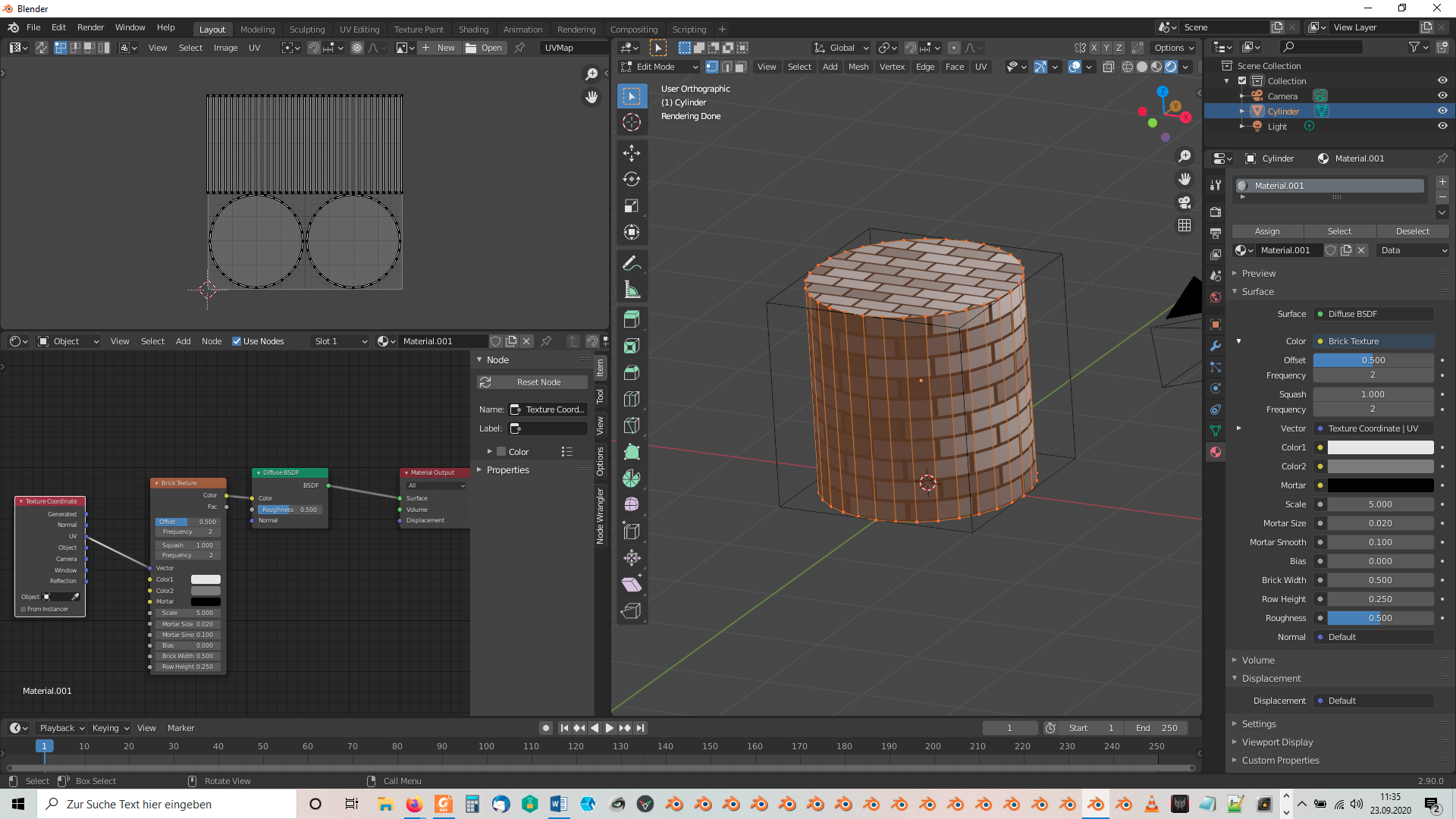
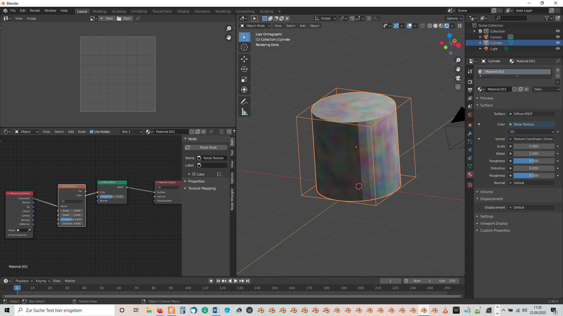
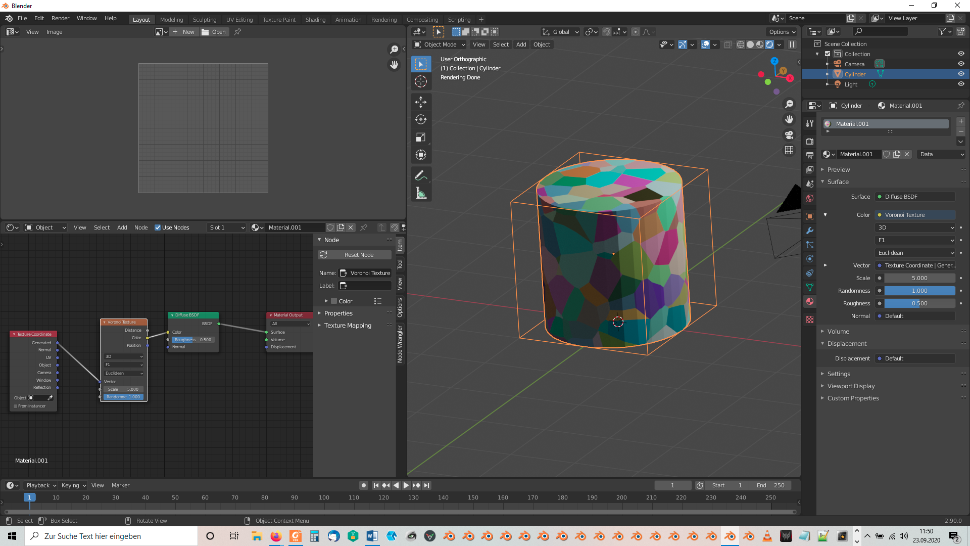
This is possible because Blender 2.8 and 2.9 when adding a mesh primitive to your scene automatically generate a UV map. Of course you could create your own custom UV map if needed. As your can see, the UV map lies in a flat plane so that the “Flat” projection method used for “Brick Textures” brings this pattern on your UV map which is then wrapped around your 3D object. A “Noise Texture” or a “Voronoi Texture” for example show in contrast to a “Brick Texture” als variations in the third dimension so that they aren’t stretched in that way (as long as you don’t do any manual scaling in that dimension off course!):
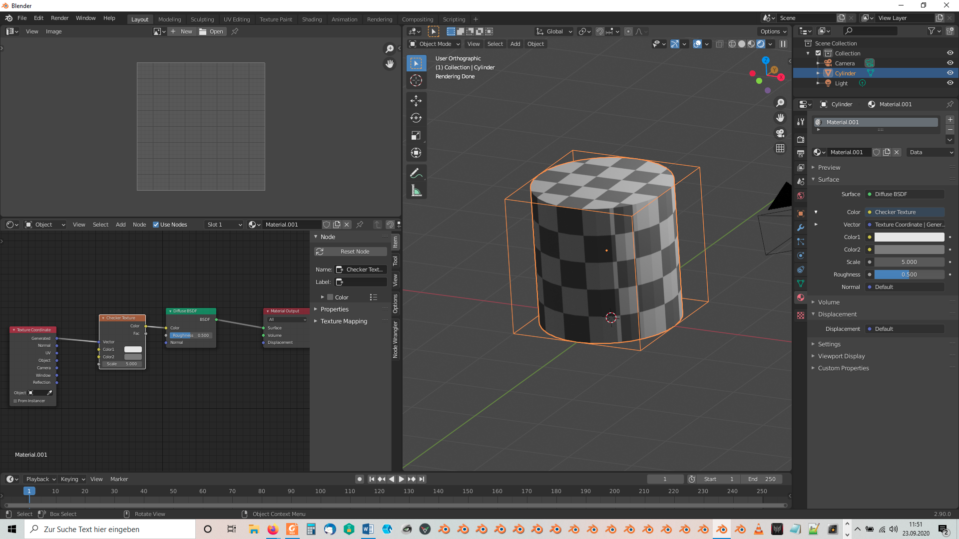
The “Checker Texture” also works fine in that sense but has no gaps for the mortar:
Using a “Mapping Node” and rotating around the object’s local X axis doesn’t work since it causes an uneven pattern:
-
AuthorPosts


- The topic ‘Darius’s Blender progress’ is closed to new replies.