
Collab 2020: Modeling Heavy Equipment (Backhoe)
Forum Archive › Collab 2020: Modeling Heavy Equipment (Backhoe)
- This topic has 1,439 replies, 27 voices, and was last updated 4 years, 1 month ago by
Omar Domenech.
-
AuthorPosts
-
June 21, 2020 at 2:30 pm #54587
Well I shoved my pieces over by 1.8″ towards the center so @pfbourassa You’re flanges should only need to move over 1.8″ in the X direction to mate up with mine again.
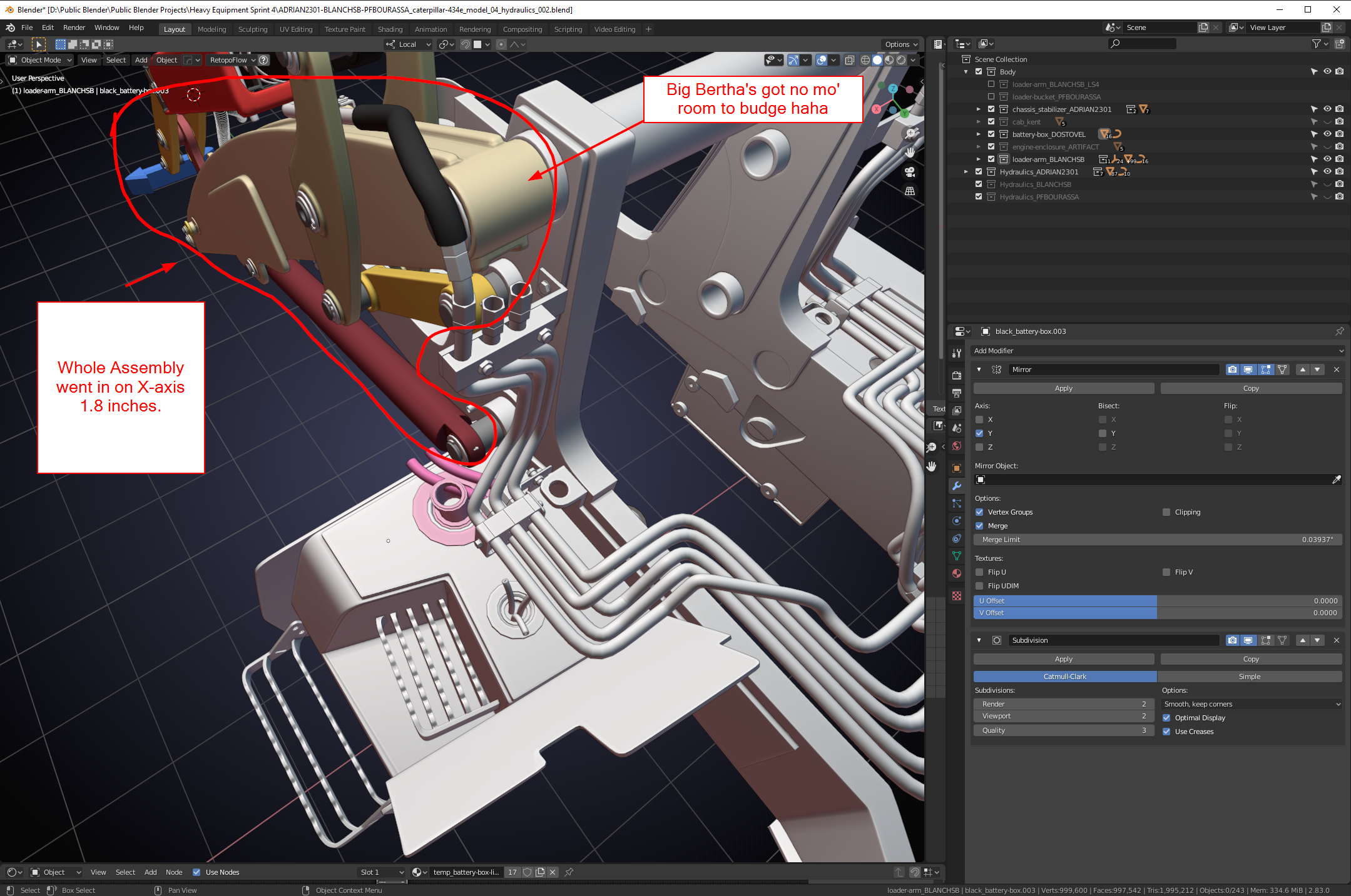
@dostovel I think that should help a bit if you’re moves out. If you could move yours out about 1.5″ or so that should be enough, OR I could do some trickery with the hydraulics and make them overlap vertically.Also @adrian2301 . I moved your upper hydraulic clamps over just a bit because they were causing hoses to be hitting into the main loader arm (big Bertha) They moved down Z a smidge and over Y a smidge. I can give you the dimensions that I moved if you need them but I don’t remember off the top of my head.
June 21, 2020 at 2:51 pm #54588Here’s my file for reference: Collaboration File: https://www.dropbox.com/s/v9d7k3n8ybzy2h7/ADRIAN2301-BLANCHSB-PFBOURASSA_caterpillar-434e_model_04_hydraulics_002.blend?dl=0
It’s not done but I figured it is a good time to begin sharing these details.
June 21, 2020 at 11:34 pm #54589Well, now I feel like an idiot. I have more conflict findings, and I am guilty of it too.
I took this from Kent’s posting on his Digger Arms:
For the black lines (which seem thicker in photos) I’ve gone with 3/4″ diameter and for the metallic lines I’ve gone with 1/2″.
@adrian2301
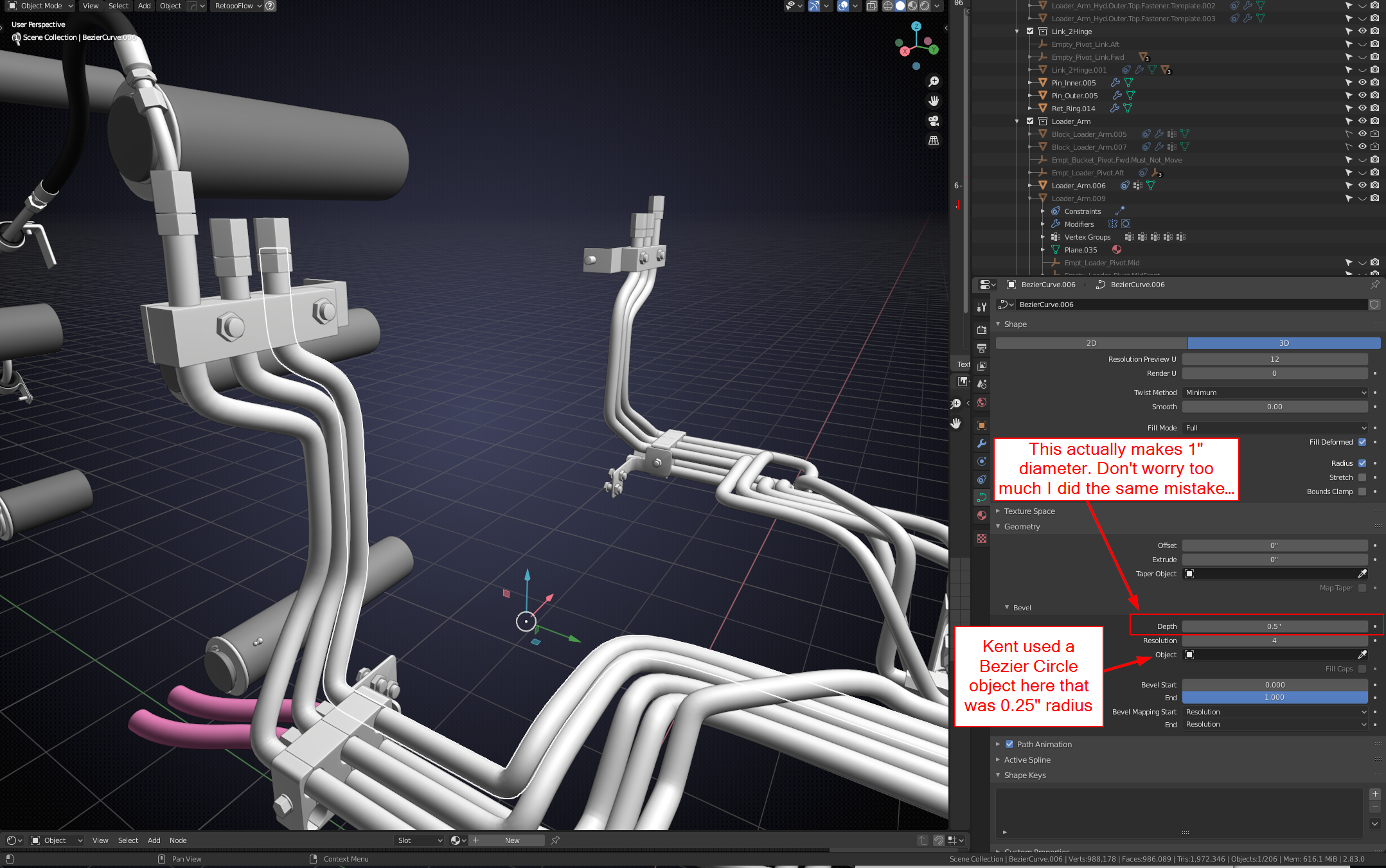 The hose diameter is 3/4″ (0.75) and the metal tubing diameter is 1/2″ (0.5).
These hoses on the bezier curve are using radius instead of diameter if you do not specify a Bevel Object and instead use a Depth (apparently Depth means radius)
If you specify a Bezier Circle as the Bevel Object then the initial width on the Bezier Circle creation menu is also a radius………….(face to palm, then palm to desk, then head banging palm on desk, because the palm provides padding)……..
So, basically all of my hoses are double the size they needed to be.
I made the fitting today and realized something was amiss when I actually sized the fitting per actual dimensions and then noticed it was wayyyyy smaller than the hoses.
Basically all of the hydraulics in you’re and my file are double what they need to be.
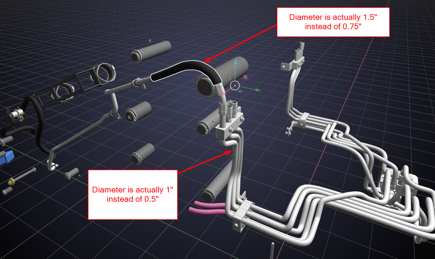
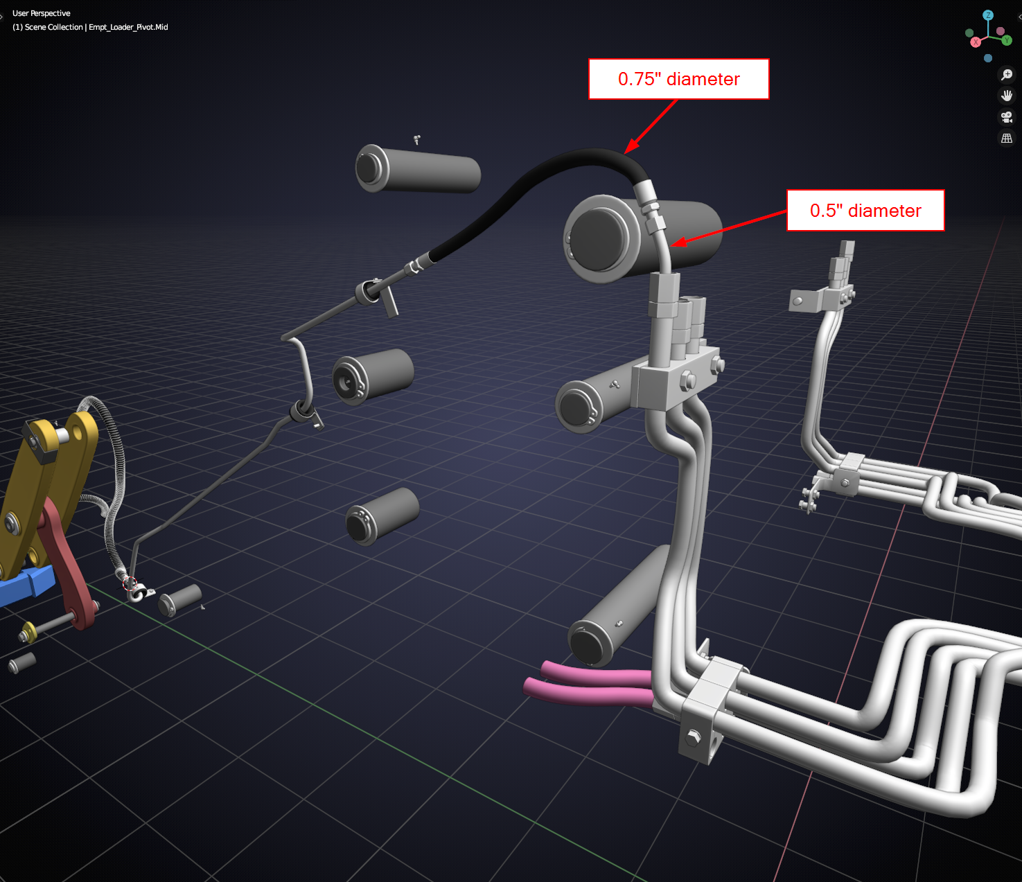
Maybe the plan moving forward should be: I will correct my hydraulics then give the file back to you to correct your assembly? Parker doesn’t have a ton of hydraulics to need to work with and he is going to make a tee that will mate up with my two lines going to him. Just P.S. @pfbourassa and all others using hydraulic lines. You may want to take note and not make the same mistakes haha.
It’s about the journey…………. 🙂
June 21, 2020 at 11:34 pm #54590Well, now I feel like an idiot. I have more conflict findings, and I am guilty of it too.
I took this from Kent’s posting on his Digger Arms:
For the black lines (which seem thicker in photos) I’ve gone with 3/4″ diameter and for the metallic lines I’ve gone with 1/2″.
@adrian2301
The hose diameter is 3/4″ (0.75) and the metal tubing diameter is 1/2″ (0.5).These hoses on the bezier curve are using radius instead of diameter if you do not specify a Bevel Object and instead use a Depth (apparently Depth means radius)
If you specify a Bezier Circle as the Bevel Object then the initial width on the Bezier Circle creation menu is also a radius………….(face to palm, then palm to desk, then head banging palm on desk, because the palm provides padding)……..
So, basically all of my hoses are double the size they needed to be.
I made the fitting today and realized something was amiss when I actually sized the fitting per actual dimensions and then noticed it was wayyyyy smaller than the hoses.
Basically all of the hydraulics in you’re and my file are double what they need to be.
Maybe the plan moving forward should be: I will correct my hydraulics then give the file back to you to correct your assembly? Parker doesn’t have a ton of hydraulics to need to work with and he is going to make a tee that will mate up with my two lines going to him. Just P.S. @pfbourassa and all others using hydraulic lines. You may want to take note and not make the same mistakes haha.
It’s about the journey…………. 🙂
June 21, 2020 at 11:39 pm #54591I think my comment posted twice…….weird? I don’t want to delete one for the fear of losing both now. Oh well. Hopefully y’all get the point.
June 22, 2020 at 12:14 pm #54592So that’s why it looked bigger than I was expecting. I watched that part of the live stream again to make sure I done the math right.
That means I will need to alter the size of the brackets also. Best if, like you said, finish yours then pass the file back to me and I can adjust them.
Let me get this right then, all I need to do is divide the bevel depth in half???
Looking at your parts in the second image above the size does feel right compared to the first
June 22, 2020 at 12:45 pm #54593So, yeah. I typically agree with Kent by using a bezier circle as the template “Bevel object” because you can control all hydraulics that are using it dynamically rather than going through them 1 by 1 by 1 by 1 by…………ugh….
Yeah @adrian2301 the diameter is just double the radius so dividing the “Bevel Depth” would work but again I already created 2 Bez circles as templates for the diameter if you just want to assign those. I can put them in their own collection next to the other hydraulics collections. Then @pfbourassa and @adrian2301 and @blanchsb and whoever else can all use the same template if a decision comes later to change the hydraulics’ diameter….. We would just adjust the circle’s diameter and everything else would be adjusted (except the fittings).
June 23, 2020 at 10:40 am #54594Starting to collect showreel / exploded view inspiration 🤩
June 23, 2020 at 10:46 am #54595Okay. I actually think I can give the file to both Parker and Adrian. @pfbourassa you should be good to go, I made some notes on the sheet in the file, take a look for our comments. we can regroup at the end and append our files as one or submit them separately. I am up for either way. I still have some work to do on my hydraulic connectors to my pistons and a few other details to add but I can work those on my own.
Here’s my file: DropBox – Upload Adrian2301-Blanchsb-Pfbourassa
@adrian2301 I have made a few adjustments to the hydraulics going to my connection points. If you just want to make them yourself you can re-append your collection. I had to move the brackets around because they were too close to the lower hydraulic and upper hydraulic. I adjusted your lines to stay in line with them. There left and right brackets were also not mirrored about the world origin so I fixed it so the left side matches the right side (brackets only) and then adjusted the hydraulics for that as well.
Again, if you want to look things over and do it on your own that is fine too. I figured since I was in the thick of it I might as well do a couple of adjustments so that all you have to do is scale most things by 0.5.
The brackets should be the hardest part for the scaling but you can get creative in edit mode and get similar results.
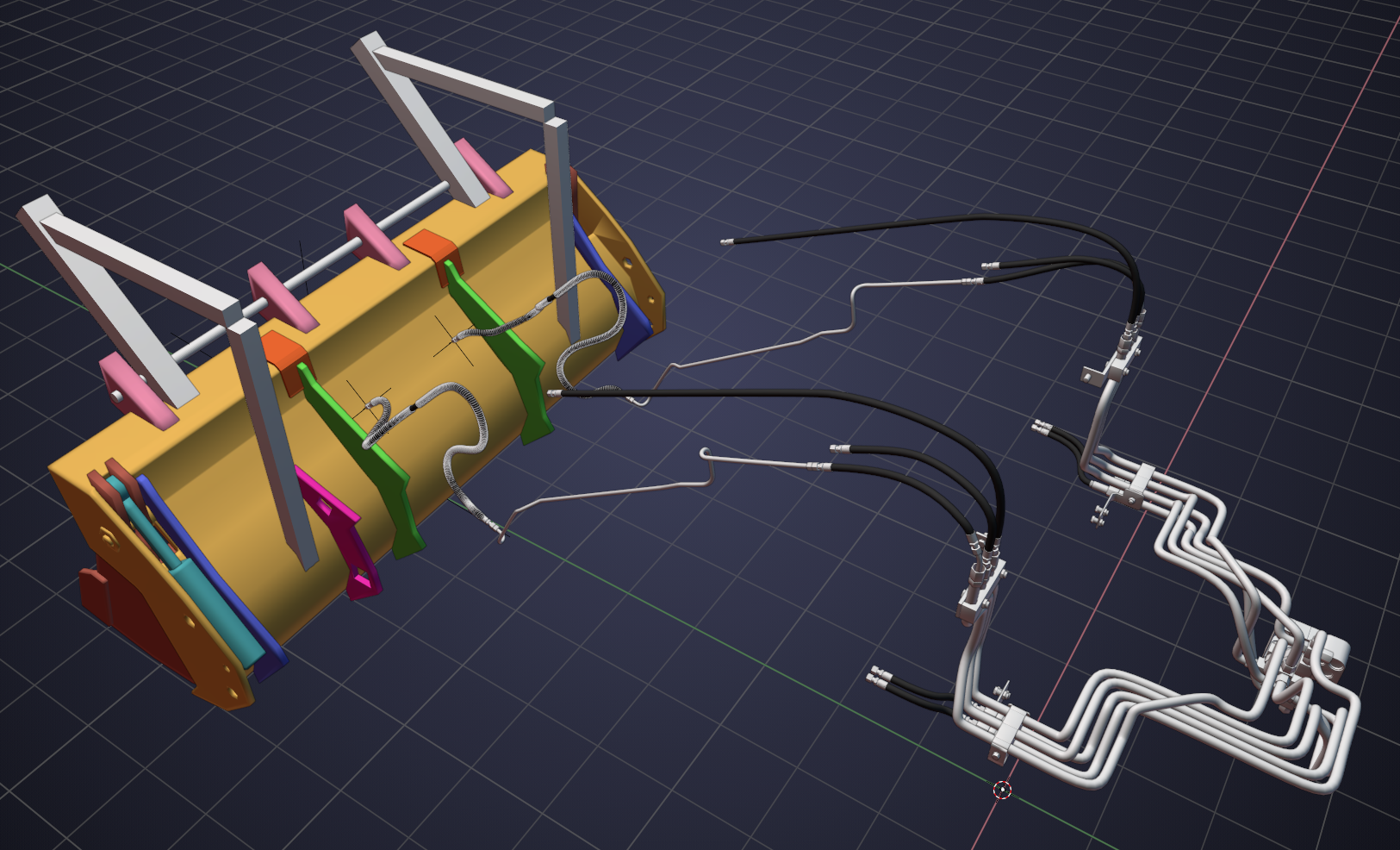
Looks pretty cool seeing these lines all come together:
 June 23, 2020 at 10:49 am #54596
Woah! That was awesome! I wonder how long that took to animate? Let alone render????
June 23, 2020 at 12:12 pm #54597That is awesome…
If anyone thinks that is happening with our engine, see you in about 3 years. ha ha.
June 23, 2020 at 12:14 pm #54598Hey @adrian2301. I posted the file back to you down below. Sorry, it’s buried down a ways now since this topic is ever growing.
June 23, 2020 at 12:16 pm #54599@adrian2301 haha no no, this is not my expectation for the engine. Rather apply this idea to the entire backhoe of which the engine is only one part. I think that could work quite well.
June 23, 2020 at 12:16 pm #54600Nice. @blanchsb I will download your file and make my adjustments and send it back. I think uploading one file with all our names on it will be ok with @theluthier
June 23, 2020 at 12:19 pm #54601
-
AuthorPosts


- The topic ‘Collab 2020: Modeling Heavy Equipment (Backhoe)’ is closed to new replies.