@duerer that node setup is definitely not made by a genius 😉
Plugging a value (output from the Math Node) into a vector socket, means that the X, Y and Z of that vector all get that same value. To then separate the X, Y and Z and only use the Z….That person has absolutely no idea what he/she is doing.
Without the separate XYZ, it would be something like this:
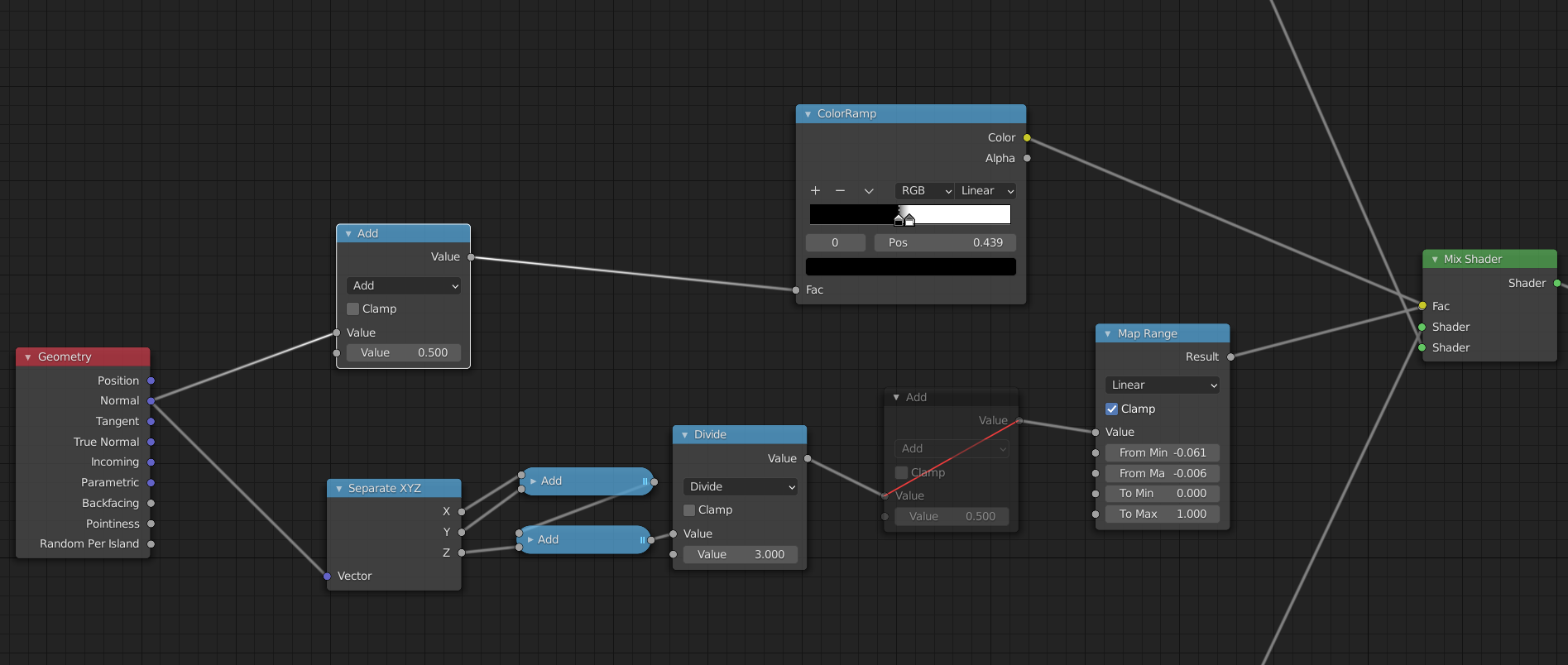
Both ‘paths’ give the exact same result. I muted the Add node and subtracted 0.5 from the ‘From Min’ and ‘From Max’ in the Map Range (which you cannot do with the ColorRamp).
In words: the creator of this node setup has made an (imaginary) diagonal plane (which has a Normal Vector pointing in the direction (1, 1, 1)) and looks at how close the Normal of each polygon of the Object that uses this shader, is to that Vector (1, 1, 1). And all this in, what I would call, a clumsy and very unintelligible way…

